Wiring Schematic for Spdt Variable Switch

Thread Starter

mpate

Joined Jan 11, 2019
6
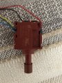
Good day everyone. I am in the middle of converting this Spdt trigger switch from a 58V weed trimmer. I looked up the model of the switch with availability of the wiring schematic. I want to convert this to dial variable speed switch, but I can’t identify the wiring for the controller. This runs a brushless motor. The switch model is defond EGA-1101F. Any helpnwould be greatly appreciated. Any links to possible switch replacements would be great.
 

Attachments

jpanhalt

Joined Jan 18, 2008
11,087
Welcome to AAC.

There are 5 wires to that switch. Very likely, it switches something that then switches the motor (e.g., an electronic motor switch) along with some safety interconnects. Putting a variable resistor or voltage supply in one of the leads will probably not change the motor speed.

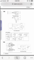
When you looked up the schematic, what did you find? Can you share it with us? A brushless motor that is variable speed is not simply controlled by voltage. Modelers us an "ESC" for those motors.
 

jpanhalt

Joined Jan 18, 2008
11,087
Thanks for sharing the schematic. I would start with identifying the three wires to the variable resistance. Two will have a constant resistance. One will have a variable resistance to either wire. The sum of the variable resistances will equal the fixed resistance. The measure voltage to the negative pole of the battery. that will tell you with certainty those wires. Those are the ones you connect your pot to. Leave the others as is, i.e., on/off and reverse.
 

LesJones

Joined Jan 8, 2017
4,511
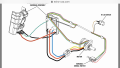
I think it is very unlikely that anyone will know the colour coding of the wires on your trimmer. If one of the switches in the diagram in post #4 is the switch in your trimmer it should be possible to work out the colour code from that diagram. The picture in post #1 does not seem to match either one. I suspect the green , blue & yellow wires in the picture in post #1 are from the potentiometer. You will need a multimeter to identify the ends of the track and the slider. You will also need to measure it's resistance to select a potetiometer of the same value to replace it. For your application you probably don't need the set of normally closed contacts that perform the braking function.

Les.
 

Thread Starter

mpate

Joined Jan 11, 2019
6
Gentlemen, I appreciate the help. I will look through what you all have mentioned and try to find a reasonable solution. Thank you all!
 

jpanhalt

Joined Jan 18, 2008
11,087
That has a lot more wires than the switch yo show. Do you have a multimeter with which you can test? Why do you seem to not want to do that?
 

Thread Starter

mpate

Joined Jan 11, 2019
6
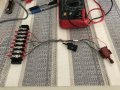
Gentle so here is what I have come up with. I added the 7 wires coming off then 2 switches to a block and tested the voltage before the trigger on the variable speed switch is pressed and after it is pressed. Here is the results. What I am looking for is where I can place it radial or rotational switch instead of one, so you don’t have to keep it pressed.

Depressed and then triggered voltage.
  1. Red 57v / 9.6
  2. Yellow 57v / 4.6
  3. Green 57v / 0
  4. Blue Is the negative
  5. White 0v / 0v
  6. Brown 57v / 9.6
  7. Black 57v / 4.6
Would I need to find radial variable switch that has the same resistance built in to drop the voltage to the same levels? I thought this would have been a simple swap of a variable switch. Any help would be appreciated.
 

Attachments

Top