 Facebook
 Google
 GitHub
 Linkedin
Hi, im currently stuck on a a circuits project, first time ever doing anything like it. I have a general idea of how relays work, but having trouble making it work with my project. The project consists of 3 entry ways, 2 using magnetic reed switches and the other a simple spst door switch. one of the reed switches has a bypass switch to deactivate the trigger to only that switch (garage). And a key switch at the beginning of the circuit makes it all happen, and an led to show the system is armed. When any trigger go off, a buzzer is supposed to sound and keep ringing even if an entry closes again. 6V battery and 6V relay are also included.
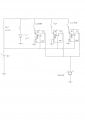
Now, about the relay, from something a friend of a friend who knows circuits showed me, he gave us an example of what our circuit should follow. I will attach the picture. when i followed this, assuming it hooked it up all right, the buzzer immediately goes off when the batter is turned on and will only shut off if i turn on the system with the key switch. I'd like to know if the diagram is not correct to see if maybe i made a mistake.
Second thing is more for theory.
Another way we tried wiring the relay ealier invovled one loop for the entry way triggers connected from NO to coil, and another loop for the buzzer from NC to negative end of the battery, i will attach a picture of something i found online that represents it. Unfortunately, while this worked perfectly, it required shorting com to NO to work at all, otherwise the buzzer would sound. I was wondering if there was a way to improve upon this. I've tried switching the trigger loop to NC and the buzzer loop to NO, thinking i wouldnt need to short from com to NO since the trigger loop would be armed as soon as the system is armed. This didnt work for me so im wondering if it doesnt make sense or maybe i messed up the circuits.
Sorry for the long post but we've been struggling with this for the past week now.
Attachments
-
 91.6 KB Views: 28
 -
 3.7 KB Views: 22
Last edited:


