Wiring diagram for a motorised zoom lens

Thread Starter

JoeCK

Joined Mar 20, 2020
73
Hello,

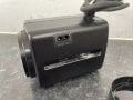
I have Ernitec 6-90mm Motorised zoom lens and would like to fix it onto a microscope.

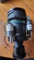
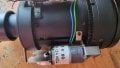
This lens has 2 motors. One connected to the front lens and another to the back lens. Please see the attached images.

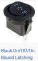
The motors are 12v 1A and the polarities (positive and negative) can be reversed to move the gears forward and reverse for zoom-in and zoom-out functions.

Now I would like to figure out the best wiring connections for the front motor and back motor for the zoom-in, zoom-out, and fine-tune purposes.

Any help would be greatly appreciated.

Cheers,
 

Attachments

MisterBill2

Joined Jan 23, 2018
27,186
The circuit can be exactly the same as has been presented many times in this forum: two SPDT switches, buttons in this case, with the motor connected to the common of each switch, the negative supply connected to the NC contact of both, and the positive connected to the N.O contact of both button switches. BUT the TS will need to add a current limiting arrangement to avoid damaging the mechanism when the end of motion is reached.
 

Thread Starter

JoeCK

Joined Mar 20, 2020
73
The circuit can be exactly the same as has been presented many times in this forum: two SPDT switches, buttons in this case, with the motor connected to the common of each switch, the negative supply connected to the NC contact of both, and the positive connected to the N.O contact of both button switches. BUT the TS will need to add a current limiting arrangement to avoid damaging the mechanism when the end of motion is reached.
Thanks Bill

I think got kinda idea of the thing... (not expert) However, can you pls draw a quick rough pen sketch on paper?

Also, what type of spdt switches will be right in this application pls? Attached pictures.

Regarding TS limiting current, this particular model is a Japan make and they have added a freewheeling gear system once it reaches either ends for both the front and back motors
 

Attachments

Tonyr1084

Joined Sep 24, 2015
9,744
What @MisterBill2 is describing is pictured below (post #5). In the drawing each switch is a momentary type of switch. It doesn't need center off, but you could if you wanted to. In this configuration when both switches are NOT pressed the motor has power on both motor leads. This doesn't use power but it acts like a dynamic brake, stopping the motor from turning. When you press one switch you apply a negative to one of the motor leads. Pressing one button will slew the motor in one direction; pressing the other button will slew the motor in the opposite direction. If you press BOTH buttons at the same time nothing will happen because both of the motor leads will be tied to negative.

This drawing shows power being held on the motor leads at all times. You can just as easily wire it the other way. Give me a few seconds and I'll bang out the opposite drawing showing the alternative.
Screenshot 2024-09-17 at 8.57.56 AM.png
 
Last edited:

Tonyr1084

Joined Sep 24, 2015
9,744
In case you're unfamiliar with symbols, the triangle at the bottom represents a common or common ground. The triangle at the top represents a voltage source. Since you're using 12V you can simply put 12V at the top and -12V at the bottom. Not suggesting a 24V source, no. Just that if using a battery the positive would be 12V and the negative would be -12V. The two black dots represent wire junctions. If a wire crosses another wire without the black dot there is no connection between them. Only when the black dot is present does it represent a connection.
 
Last edited:

Tonyr1084

Joined Sep 24, 2015
9,744
You say you have two motors. Are they both controlled by the same circuit? Or is each motor independently controlled? If both motors are controlled by the single circuit then you would wire the motors together. If independently operated then you'll need a circuit for each motor. The circuit will be the same either way.
 

Tonyr1084

Joined Sep 24, 2015
9,744
Both motors will slew at the same time. If one motor has to run opposite to the other then simply reverse two leads of one motor. Need a picture?
Screenshot 2024-09-17 at 9.22.01 AM.png
 

Tonyr1084

Joined Sep 24, 2015
9,744
Unless the motor & gear assemblies have built in limit switches.
Screenshot 2024-09-17 at 9.49.30 AM.png
These are Normally Closed Limit Switches. When you press the "Close" (or zoom in) button the motor will slew until the Close Stop switch opens. When you push the "Open" (or zoom out) button the motor will slew through the right diode until the NCLS switch closes. The motor will continue to slew until the Open Stop switch opens. And vice versa.
 

Thread Starter

JoeCK

Joined Mar 20, 2020
73
In case you're unfamiliar with symbols, the triangle at the bottom represents a common or common ground. The triangle at the top represents a voltage source. Since you're using 12V you can simply put 12V at the top and -12V at the bottom. Not suggesting a 24V source, no. Just that if using a battery the positive would be 12V and the negative would be -12V. The two black dots represent wire junctions. If a wire crosses another wire without the black dot there is no connection between them. Only when the black dot is present does it represent a connection.
Thanks for the details. I was about to ask you about these :)
 

Thread Starter

JoeCK

Joined Mar 20, 2020
73
Both motors will slew at the same time. If one motor has to run opposite to the other then simply reverse two leads of one motor. Need a picture?
View attachment 331836
Thanks a lot Tony :) you are a STAR!

I was about to ask about this possibility. However in a bit different way though.

There are two motors as in the picture of the zoom lens (in the first post). One for the front lens and the second for the back lens part. Both the motors need to function (forward/reverse) independently for focusing purposes. At the moment we will end up using 2 SPDT momentary switches for each motor totalling 4 SPDTs.

Can we use 1 DPDT switch (by tweaking the wiring) for each motor, so there are 2 DPDTs, and helpful to accommodate/space them inside the shell case pls?
 

Thread Starter

JoeCK

Joined Mar 20, 2020
73
True. Unless the motor & gear assemblies have built in limit switches.
Yeah, when I checked it's not like a switch... more of a freewheel mechanism there in the gear system. So when the lens reaches either end the gear wheel starts to slip saving the motor from stalling.
 

Thread Starter

JoeCK

Joined Mar 20, 2020
73
You say you have two motors. Are they both controlled by the same circuit? Or is each motor independently controlled? If both motors are controlled by the single circuit then you would wire the motors together. If independently operated then you'll need a circuit for each motor. The circuit will be the same either way.
There is no circuit as such. Just one set of wires from each motor and those wires seem to be reversible as well for forward and reverse motion of the lens sections.
 

Tonyr1084

Joined Sep 24, 2015
9,744
There are two motors as in the picture of the zoom lens (in the first post). One for the front lens and the second for the back lens part. Both the motors need to function (forward/reverse) independently for focusing purposes. At the moment we will end up using 2 SPDT momentary switches for each motor totaling 4 SPDTs.
For independent motor control you will need four switches; two for each motor.
Can we use 1 DPDT switch (by tweaking the wiring) for each motor, so there are 2 DPDTs, and helpful to accommodate/space them inside the shell case pls?
Will have to think on this tonight.
There is no circuit as such. Just one set of wires from each motor and those wires seem to be reversible as well for forward and reverse motion of the lens sections.
This confuses me. You have two motors but no control circuit at present? Or are you trying to build the entire thing from scratch to control zoom and focus? Is this from another camera? Looking at the pic's your "camera" did not originally have zoom and focus capabilities.

Will have a look back this evening.
 

MisterBill2

Joined Jan 23, 2018
27,186
USUALLY the two adjustments are ZOOM and FOCUS, which are not at all the same, and so there will need to be separate circuits.
The switches shown could work if they have six terminals (If they are DPDT switches.) I could not tell. My X-Ray vision is even poorer than my mind reading .
 

Ya’akov

Joined Jan 27, 2019
10,226
So, it appears that the front motor is used for focus (moving the front element group) and the back motor of zoom (moving the zoom group). Since the is no visible feedback mechanism I assume it used an autofocus system. Since there is no limit sensing, it must have used over-current to detect end of travel.

The best way to adapt this would be to turn the motors into servos of the simplest kind by adding position sensing and some circuitry to allow PWM control—like a hobby servo. This would allow the use of two knobs that would always move the elements to the same position for any particular rotation.

Though relatively simple for someone with a clue, it is certainly more complicated than a pair of switches. But it would seem to be very challenging to achieve sharp focus with a switch like that. I can imagine it being very frustrating shuttling back and forth past focus until you managed it.
 

Ya’akov

Joined Jan 27, 2019
10,226
Let me add that if my surmise is correct, and focus is difficult, you could try adding a switch the adds an appropriate resistor dropping the voltage to the motor—and so the speed—for ”fine” control.
 

MisterBill2

Joined Jan 23, 2018
27,186
I have a few video cameras that have zoom and focus adjustments controlled by momentary switches, rather similar to what I described. there are no problems with getting into focus. A microscope will probably be different, but if the speed is not excessive it should not be a problem. So it might need a PWM drive so as to have enough torque without the speed. A fixed speed PWM drive just for the torque.
 

Tonyr1084

Joined Sep 24, 2015
9,744
Can we use 1 DPDT switch (by tweaking the wiring) for each motor, so there are 2 DPDTs, and helpful to accommodate/space them inside the shell case pls?
No. You're going to need two sets of switches. Mini-Microswitches like these and you don't need toggle switches. These offer a very small package. All you need to do is create a toggle
 
Top