wiring and control method to connect an arduino to a PWM dc controller

shortbus

Joined Sep 30, 2009
10,049
O: yes? I was commenting on my problems with posting to email lists.
*** apparent rules for email groups (mc-chassis, Feet-Forward, MC-engines, Tilters - in that vein, anyway.)
1) no sequential threads where you are the only poster-ie "blogs".
They have to be conversational.
2) You get grizzled at for asking "lazy" questions, or not researching the accumulated body of literature. If I did that I would never
post anything-having been "there" for several years... !
3) preferably postings have to be "newsy" - ie about events, stuff you have actually made, interviews, test rides etc.
4) don't post a lot-it clutters up the digest reports with stuff practically nobody wants to read, or "wade through".
I find that a bit pointless, frustrating, and useless to me, so I tend to "break the rules", and get suspended from posting.

I also think that readers find some of my posts irritating, which is less of a problem on a forum: you just don't follow that thread, board,
or person.
Well, enough is enough. I am shifting elsewhere, and I suppose I should stop moaning about it.

And after all of your problems, you still don't see YOURSELF as the root of the problem?

To your point #2, this has been my problem with you. You have no experience with the back round of doing these types of things and yet you insist your way is the correct way. To borrow from one of your blog posts, you claim the brazing a frame joint is far superior in both strength and ease of doing it, in stead of welding. That statement is just flat out wrong and dangerous. Someone following your blog and doing as you tell them could/can get either hurt or killed. Brazed butt weld type joints are not used in frames for a reason, they fail. The same with you telling that a 1mm wall tube is what is needed in the frame. I could go on but won't.

You need to do some real world, long term research into what is both safe and what works, before making such outrageous and wrong claims. Doing this type of thing is why you get treated badly on web sites catering to what you want to do, by people that do that type of thing their whole life. Stop acting like a self centered fool. In these days of the internet the real trusted information is readily available most of it for no cost other than you internet connection. Use it to come up to speed, so you can discuss things looking like you have a little knowledge. I'm not trying to be harsh or condescending with my talk, but trying to show you a path forward to your end goal.
 

Thread Starter

Owen Nieuwenhuyse

Joined Jun 20, 2017
42
And after all of your problems, you still don't see YOURSELF as the root of the problem?

To your point #2, this has been my problem with you. You have no experience with the back round of doing these types of things and yet you insist your way is the correct way. To borrow from one of your blog posts, you claim the brazing a frame joint is far superior in both strength and ease of doing it, in stead of welding. That statement is just flat out wrong and dangerous. Someone following your blog and doing as you tell them could/can get either hurt or killed. Brazed butt weld type joints are not used in frames for a reason, they fail. The same with you telling that a 1mm wall tube is what is needed in the frame. I could go on but won't. /*

O: This information came straight from the MC-Chassis-Design email group, from respected professional frame builders.
1) You don't use brazed tube butt joints, but natural "T" joints. The brazed joint made in this way is generally stronger than the parent tube.
2) Any brazed butt joint should be sleeved or lap-plated. Same goes for any kind of welded butt joint with a lot of load on it, but
particularly tensile and bending loads.
3) 1mm tube is adequate if strength and stiffness has been properly evaluated. larger bore tubes that thin in mild steel have a tendency
to dent in a crash, so if you are planning to crash a lot, use heavier tube, or something like chrome-moly tube.
ie: motocross bikes.
Test loading specs are more important. for main frame members, I would suggest about 5Gs . Commercial frames use 10mm high tensile
bolts to hold everything together. I think that a 4mm end plate and a 20x20x1.5 frame rail is adequate to take the same "proof" load
as a metric grade 8.8, 10mm bolt. You may oval out the plate hole a bit, so the plate should be about 30mm wide to avoid
tearing the eye out of it. This is for straight tensile loading only. If you expect significant bending loads, than you have to work
out how to resist them in addition.
*/
You need to do some real world, long term research into what is both safe and what works, before making such outrageous and wrong claims. Doing this type of thing is why you get treated badly on web sites catering to what you want to do, by people that do that type of thing their whole life.
/*
O: see my points above. I get good technical information from professionals Have a look at the email list I mentioned.
*/
Stop acting like a self centered fool. /*
O: That is an unsupported and troll-like accusation. I generally back up anything I say with reasonable arguments. It is not my fault if you lack the background to understand my arguments. I may combine terminology from two different fields in a way that is unfamiliar to you, but they go well together, and get good results.
Regarding self-centered: It is not my fault that I am a little socially inept, and not good a gauging people's reactions. That is inherent in my makeup, and there is nothing that I can do about it. So far I have done alright just being me! :)
*/ {open a comment block-possibly slightly off-target, but it is shorter than [QUOTE/] }

In these days of the internet the real trusted information is readily available most of it for no cost other than you internet connection. Use it to come up to speed, so you can discuss things looking like you have a little knowledge. I'm not trying to be harsh or condescending with my talk, but trying to show you a path forward to your end goal.
O: um - sounds a bit like trying to teach Grandmother to suck eggs -I have been at this Internet thing for a few years.....

Really, if you actually research some of the points I have mentioned in my posts and arguments, it will improve your ability to
understand the points, and help you to evaluate mechanisms and designs a lot better.

Nowdays, I think they make even toolmakers take similar courses, so I suppose you have seen it in the (distant) past, but have
forgotten that stuff through lack of use. (some may have come from the info-systems side, so you may not see the material in that format in a basic mechanics (of machines) course.)
 

shortbus

Joined Sep 30, 2009
10,049
You are a lost cause. Go on being "you" and not getting the help you claim to want. I tried to help but you don't want to or can't get out of your own way. Be isolated and do it your way, even though the rest of the world does it differently.
 
Last edited:

Thread Starter

Owen Nieuwenhuyse

Joined Jun 20, 2017
42
You are a lost cause. Go on being "you" and not getting the help you claim to want. I tried to help but you don't want to or can't get out of your own way. Be isolated and do it your way, even though the rest of the world does it differently.
1) I don't claim to need help at the moment. I was just enjoying a nice chat.
2) I don't consider myself to be a "cause" to this group, so I can't be "lost" in that way. I am interested in online discussion of motorbike "stuff",
plus possibly related topics. Leading to who knows what?
3) Isolated how? Because nobody will respond to my emails? I have a lot of motorcycle-related groups to try yet, then there is Usenet mail
groups. I don't think I get a usenet feed with this provider- I will have to research that. I used to be on a few usenet groups around 10 years ago,
but let them drop I suppose they may have amalgamated with someone else by now.
4) Do what my way? I haven't proposed anything really strange yet that no-one has done at all.
Maybe my idea for a motorcycle frame composed of a 3D lattice of square, straight, tubes is a little unusual.

The idea is based on a Formula Ford frame I saw many years ago. That used a little heavier tube than I am proposing, but
There were requirements with the car chassis:
a) not to wrap the driver up in bent tubing in a crash. The motorcycle has less of an enforced requirement to work
like that, but is also less likely to be involved in a crash/end-for-end loop/flying through the air at high speed; antics. I do intend to have an
integrated rollbar to assist in holding the seat area together under ground impact, which reduces the risk of neck injury. I also want to use
4-point seatbelts to prevent rider ejection, as there is some encapsulation.
It would need a forward hoop to help prevent neck injury/death in a fully inverted ground "hit". I may consider adding that provision....

b) to provide twist stiffness in a hollow tubular format-, and to resist corner wheel loading.
I can sidestep using a strong anti-twist lattice structure by using the motor as a central stressed member.
Also, motorcycles have less need to be axially stiff as the only twisting loads are angled bump response and axial oscillation.

c) to tolerate much higher "G" loading than I need, due to stiffer suspension.
 

shortbus

Joined Sep 30, 2009
10,049
1) I don't claim to need help at the moment.
Every thread you have started here is a question for help.

3) Isolated how? Because nobody will respond to my emails? I have a lot of motorcycle-related groups to try ye
By your own words you have said people tell you to leave or just don't respond to you. And you still say it has nothing to do with how you approach people and their hard earned knowledge as being wrong and your way is the best.

The idea is based on a Formula Ford frame I saw many years ago.
The very first site I went to and read about Formula Ford frames is probably where you got your idea about brazing a frame, I'm guessing. But like all of our conversations you picked one little piece of the topic that suits YOUR idea, instead of taking in the meaning of the whole paragraph. Sure it says that they were 'sometimes' joined by brazing, but you totally missed the dates they were doing it, 1954 - 1958. You missed the part about, "These tubes were generally brazed together but later, tig and mig welding became the norm." And the part about, "Chassis strength and torsional rigidity relied on triangulation, small gusset plates and a rigid belly pan riveted to the underside of lower members." Not something done in a motorcycle frame. From, http://www.thekentlives.com/index.php/tech/chassis/
 

Thread Starter

Owen Nieuwenhuyse

Joined Jun 20, 2017
42
Every thread you have started here is a question for help.
O: the start of the threads were a request for help. The interaction with people like you has prompted me to look for and find solutions, so to that extent, replies have been helpful.
The verifications I have done of your clutch suggestions are not unique: I suggest that many qualified mechanical engineers would make similar assessments. The assessment results are as good as a "proof" to me that the use of an overrunning clutch in a spooling situation will not work. You should either accept my results, or independently research the problem properly, not "grump" about it. You must be mis-remembering similar mechanisms you have worked on in the past.
*/
By your own words you have said people tell you to leave or just don't respond to you.
/*
They seem to find my posts irritating or not interesting enough to chat about. I suppose:
1) they may feel I am misusing their forum with the type and frequency of my posts: solutions? Try another forum, split posts into blog references/shortcuts/hyperlinks, and only summarise in the main post?
2) They may feel that I am somehow not attempting to interact with them properly-not much I can do about that.
It is part of my fundamental makeup. I try to be even-handed, reasonable, and not insulting.

3) Possibly the occasional post can be read as being harsh and critical, but I don't attempt to make them that way.
Maybe on re-reading some of my posts, I could have phrased them in a more encouraging and conciliatory way? It is hard to fix things retrospectively.
*/
And you still say it has nothing to do with how you approach people and their hard earned knowledge as being wrong and your way is the best.

O: I think I have tried to be polite. It is hard when you accuse me of being "wrong" and "stubborn" if I don't
agree with you, and I have proved to myself that I have good reason to disagree.
I only continue to suggest that you correctly research my answers. It is not hard to do on Google- it is all there.
*/
The very first site I went to and read about Formula Ford frames is probably where you got your idea about brazing a frame, I'm guessing. But like all of our conversations you picked one little piece of the topic that suits YOUR idea, instead of taking in the meaning of the whole paragraph. Sure it says that they were 'sometimes' joined by brazing, but you totally missed the dates they were doing it, 1954 - 1958. You missed the part about, "These tubes were generally brazed together but later, tig and mig welding became the norm." And the part about, "Chassis strength and torsional rigidity relied on triangulation, small gusset plates and a rigid belly pan riveted to the underside of lower members." Not something done in a motorcycle frame. From, http://www.thekentlives.com/index.php/tech/chassis/
O: I have saved that url, thanks. I will look at some of the designs.

No, the braze idea comes from the MC-CHASSIS-DESIGN group, and it is a common way of using
chrome-moly tubing. It is also "Braze-Welding" which uses a different technique and filler rod,
and leaves a bead like TIG welding. You still flux, but use a molten pool of bronze rather than heating the whole
part and "flowing" the braze fluid in by capillary action. The strength relies on using a well-rounded bead.
It also works on mild steel, and reduces locked-in stress. A standard welded frame may need heat treatment in a fixture to stop it "winding up" when released from the welding jig. I suppose you could flame-treat each welded area with a gas torch and get the same effect. There is a bit of a risk of major misalignment if you
don't do something. I assume you have built frames like this. What is your experience of inbuilt stress?

O: if you make enough triangles, they do the same job as heavily riveted plates or sheets. A possible
advantage of riveting is to gain a better stiffness to weight ratio. The ultimate us using a monocoque tub,
but that, or carbon-fibre construction, is probably banned for that class.

O: an interesting point is if that if you have a complex, multi-tube joint, you don't really need lap plates
on the butt-welded bits in the joint. I will check that out, too
 

be80be

Joined Jul 5, 2008
2,395
With modern materials and skilled fabricators there's no functional difference. When done right, both welding and brazing are stronger than the metals they're joining, meaning the tube should fail before the joint. For most it's a question of aesthetics and price. What do you like and how much do you want to spend?
 

Thread Starter

Owen Nieuwenhuyse

Joined Jun 20, 2017
42
add-on: I have found a mechanism that would function with a gravity drop and slow pullback:
A crank/conrod. It would have fixed stroke, and needs to go over-center top and bottom to work.
It would be tricky to use with a variable bottom position, and compression-lock in the extended position.
You would need extra bits, possibly more links? Any chain component would be the reduction between
gearbox and axle drive. This is perfect for use with an overrunning bearing/clutch.
 

Thread Starter

Owen Nieuwenhuyse

Joined Jun 20, 2017
42
.
The very first site I went to and read about Formula Ford frames......And the part about, "Chassis strength and torsional rigidity relied on triangulation, small gusset plates and a rigid belly pan riveted to the underside of lower members." Not something done in a motorcycle frame. From, http://www.thekentlives.com/index.php/tech/chassis/
O: that does not look anything like the frame I remember. It was about 25x25x2 square tubing,
in "cell" spacing 6 to 8 inch, very few long straight bits at all, no front hoops,
the "floor" line swept up to the front suspension level, and the front pedals were high mounted.
It looked real difficult to get into and out of. It may have been something else rather than a Formula Ford.
I don't remember bodywork or engine: it was stripped and up on stands.
That small-cell structure is what I want to find examples of, to check different ways of doing them:
ie: proportions of angle tubes relative to "ladder" tubes, style of gusset and lap plates, etc.
You really don't need any "ladder" tubes at all, but I think The 4 main corner "runs" are useful.
Ideally, there can be 6 main tubes at every apex, with 2 of then butted to make up the front-to-back runs.
 

shortbus

Joined Sep 30, 2009
10,049
No, the braze idea comes from the MC-CHASSIS-DESIGN group, and it is a common way of using
chrome-moly tubing. It is also "Braze-Welding" which uses a different technique and filler rod,
and leaves a bead like TIG welding. You still flux, but use a molten pool of bronze rather than heating the whole
part and "flowing" the braze fluid in by capillary action. The strength relies on using a well-rounded bead.
More stuff by people like you that are "armchair experts". What you are calling 'braze welding' is done with the Tig process and bronze rod not brass which is what brazing is and no 'flux' is necessary, the shield gas takes care of the oxidation problem. Brazing is some times used in bicycle frames but even then most steel frames are welded now days. The original brazed frames used joint pieces that the tubes slid into to make the joints strong. They weren't butt joints.

It also works on mild steel, and reduces locked-in stress. A standard welded frame may need heat treatment in a fixture to stop it "winding up" when released from the welding jig. I suppose you could flame-treat each welded area with a gas torch and get the same effect. There is a bit of a risk of major misalignment if you
don't do something. I assume you have built frames like this. What is your experience of inbuilt stress?
With 'jig built' weldments the movement from welding is very small unless you are doing precision machining on it afterward. Then it gets 'normalized'. If it is something like a frame how is it going to 'wind up'? all joints are welded to each other, where are they going to go? The welding in a frame is so small compared to the size of the whole that it makes little difference. With experience in how things move when welded you can get pretty close on just adding or subtracting width in an opening, like say a rear swingarm, then you tweak it after it cools.

As far as chrome molly frames to get the full strength and advantages of welding them you would reheat treat the whole thing. Due to the crystallization of the weld joint from the heat. But unless it's for something in aerospace type things, very few people do it.
 

shortbus

Joined Sep 30, 2009
10,049
add-on: I have found a mechanism that would function with a gravity drop and slow pullback:
A crank/conrod. It would have fixed stroke, and needs to go over-center top and bottom to work.
It would be tricky to use with a variable bottom position, and compression-lock in the extended position.
You would need extra bits, possibly more links? Any chain component would be the reduction between
gearbox and axle drive. This is perfect for use with an overrunning bearing/clutch.
Still see the need to over complicate don't you?
 

shortbus

Joined Sep 30, 2009
10,049
With modern materials and skilled fabricators there's no functional difference. When done right, both welding and brazing are stronger than the metals they're joining, meaning the tube should fail before the joint. For most it's a question of aesthetics and price. What do you like and how much do you want to spend?
What context is that from? If meant toward a motorcycle frame, I know of none being 'brazed' today, by either OEMs or reputable custom builders. Early Harley's did use brazing, but they also used forged steel fittings that the tubes inserted into, then they were brazed together. Today it's welded butt joints for the most part.

Brazing gets it's strength in a tube butt joint from a very close metal to metal fit before brazing. That's where the "skilled fabricators" part comes in. Tig or Mig welding allows a larger gap between parts of the joint to be used and still be strong, due to the 'mixing' of the parent metal and the filler due to melting of the joint. Brazing can't do that, it works totally on capillary action and is limited to the strength of the filler not the strength of the parent metal.
 

shortbus

Joined Sep 30, 2009
10,049
@ Owen Nieuwenhuyse, if you are really serious abuot understanding and doing this get a copy of the book, "Motorcycle Handling and Chassis Design - The Art and Science" by Tony Foale. Then the book by by the same author and Vic Willoughby, " Motorcycle Chassis Design - Theory and Practice", while they're both mainly about racing bikes it also pertains to road bikes too. The major thing different is the thickness of tubing, race bikes can get away with thinner wall tubes to keep weight down. Since race tracks are usually smooth, pot hole free surfaces.
 

be80be

Joined Jul 5, 2008
2,395
They use welding. I would I fixed a motor cycle fame once years ago I didn't have anything to weld it so I braze it. It broke on the tube. But welding is the way to go now days.
 

Thread Starter

Owen Nieuwenhuyse

Joined Jun 20, 2017
42
More stuff by people like you that are "armchair experts". What you are calling 'braze welding' is done with the Tig process and bronze rod not brass which is what brazing is and no 'flux' is necessary, the shield gas takes care of the oxidation problem. */

O: I have never done it, but I understand it can be done with gas as well. A little flux on the rod could be handy to clean the base metal, seeing you are not melting it.
*/
Brazing is some times used in bicycle frames but even then most steel frames are welded now days. The original brazed frames used joint pieces that the tubes slid into to make the joints strong. They weren't butt joints. /*
O: we are not allowed to use the process on vehicles in New Zealand. I propose to butt weld with TIG, grind back,
and add a lap plate or lap "angle" to the outside of the joint. The inner side is to be a multe-tube T-type joint.
*/
With 'jig built' weldments the movement from welding is very small unless you are doing precision machining on it afterward. Then it gets 'normalized'. If it is something like a frame how is it going to 'wind up'? all joints are welded to each other, where are they going to go? The welding in a frame is so small compared to the size of the whole that it makes little difference. With experience in how things move when welded you can get pretty close on just adding or subtracting width in an opening, like say a rear swingarm, then you tweak it after it cools. /*
O: thank you. I will try that.
*/
As far as chrome molly frames to get the full strength and advantages of welding them you would reheat treat the whole thing. Due to the crystallization of the weld joint from the heat. But unless it's for something in aerospace type things, very few people do it.
O: Chrome moly is not usable for road vehicles, here. I will stick to mild steel.
 

Thread Starter

Owen Nieuwenhuyse

Joined Jun 20, 2017
42
Still see the need to over complicate don't you?
O: The crank and conrod is the only way your suggestion would work. There are other mechanisms which look
more suitable to my original concept. I don't think it is unreasonable to have a floating or adjustable lower lock position.
 

Thread Starter

Owen Nieuwenhuyse

Joined Jun 20, 2017
42
@ Owen Nieuwenhuyse, if you are really serious abuot understanding and doing this get a copy of the book, "Motorcycle Handling and Chassis Design - The Art and Science" by Tony Foale. Then the book by by the same author and Vic Willoughby, " Motorcycle Chassis Design - Theory and Practice", while they're both mainly about racing bikes it also pertains to road bikes too. The major thing different is the thickness of tubing, race bikes can get away with thinner wall tubes to keep weight down. Since race tracks are usually smooth, pot hole free surfaces.
O: yes, I know the author. I understand the books are out of print at the moment.
Maybe if a cheap ebook version comes up I will get one.
Re: race bikes- they usually fail from vibration-induced cracking, particularly with large twin cylinder non-counterbalanced engines, or "vibey" singles. The thinness of the material is not directly related to less loads
being applied. You could build and get approved a "racebike" frame on the road. It is just that if you crash it,
you are likely to cause tube damage.

As an aside for a more complicated and "wayout" design idea: how about rubber-mounting the steering
head? I could use bonded mounts like old british "Mini" engine mounts, with a limiting containment to
prevent catastrophic separation. Race bike builders are trying various similar sideways deflection mounts
in bikes to deal with controlled flex and sideways deflection over bumps. It would be interesting to try.
It would also assist in damping out twisting oscillations in the bike. I will have a bit of a sketch. and see how they might be incorporated. Getting accurate figures on stiffness and modulus of elasticity could be problematic. I could make comparisons with specs for the raw rubber material.
The only place you don't want flex is "Tracking" deflection of the rear wheel under thrust or chain load.
That doesn't feel so good.
 

Thread Starter

Owen Nieuwenhuyse

Joined Jun 20, 2017
42
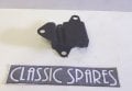
mount 4.jpg
[QUOTE="Owen Nieuwenhuyse, post: 1163671, member: 454951

As an aside for a more complicated and "wayout" design idea: how about rubber-mounting the steering
head? I could use bonded mounts like old british "Mini" engine mounts, with a limiting containment to
prevent catastrophic separation. Race bike builders are trying various similar sideways deflection mounts
in bikes to deal with controlled flex and sideways deflection over bumps. It would be interesting to try.
It would also assist in damping out twisting oscillations in the bike. I will have a bit of a sketch. and see how they might be incorporated. Getting accurate figures on stiffness and modulus of elasticity could be problematic. I could make comparisons with specs for the raw rubber material. /*
70 shore A = 3.3 Mpa
array of 4 mounts needs 0.1 degrees deflection with 50kgf at 800mm?
Torque = 400 N-m
The mount looks fairly stiff, and not intended to move far.
Needed:
1 ) stiffness testing.
2) design-in travel limits, with their own rubber buffers, to avoid too much travel and overloading.
4 units could be mounted horizontally just behind the steering head tube., staggered in 2 layers.
 

Thread Starter

Owen Nieuwenhuyse

Joined Jun 20, 2017
42
View attachment 132367
[QUOTE="Owen Nieuwenhuyse, post: 1163671, member: 454951

As an aside for a more complicated and "wayout" design idea: how about rubber-mounting the steering
head? I could use bonded mounts like old british "Mini" engine mounts, with a limiting containment to
prevent catastrophic separation. Race bike builders are trying various similar sideways deflection mounts
in bikes to deal with controlled flex and sideways deflection over bumps. It would be interesting to try.
It would also assist in damping out twisting oscillations in the bike. I will have a bit of a sketch. and see how they might be incorporated. Getting accurate figures on stiffness and modulus of elasticity could be problematic. I could make comparisons with specs for the raw rubber material. /*
70 shore A = 3.3 Mpa
array of 4 mounts needs 0.1 degrees deflection with 50kgf at 800mm?
Torque = 400 N-m
The mount looks fairly stiff, and not intended to move far.
Needed:
1 ) stiffness testing.
2) design-in travel limits, with their own rubber buffers, to avoid too much travel and overloading.
4 units could be mounted horizontally just behind the steering head tube., staggered in 2 layers.
O: I will shift this to a new topic:
Motorcycle-related bits and pieces??
 

shortbus

Joined Sep 30, 2009
10,049
O: The crank and conrod is the only way your suggestion would work. There are other mechanisms which look
more suitable to my original concept. I don't think it is unreasonable to have a floating or adjustable lower lock position.
Again, your going to have to show me this whole 'crank and con rod' thing. And do this drawing without your meandering wording and 'force vectors' on it. That may mean something to you but it just complicates things in the long run.(where have we heard that before?) What is going to stop your 'crank/con rod' from going over center? Or for that matter rotating backward when it doesn't make it to center?

And you evidently didn't even look at my drawings I made for you. They had the "adjustable/floating lower lock", using the 'spot brake' you were talking about many, many posts ago.
 
Top