Wiring a DC motor with 2 switches.

Thread Starter

exeter_acres

Joined Dec 7, 2009
11
New here...

I did search, but didn't find this...

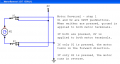
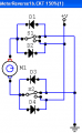
I would like to control a DC motor with 2 separate switches.
One for forward and one for reverse.
This is just a basic 2 wire motor.
I have done this before with a DPDT switch, but would really like to do this project with two separate switches..

any help on a wiring diagram would be great!

Thanks
Exeter
 
Last edited:

Thread Starter

exeter_acres

Joined Dec 7, 2009
11
Hmmm...

I was going to use the 2 switches just for looks (one with a red toggle cover, and one with a green)
but may just go with the good ole DPDT switch as it is much easier to set up..

from the link above (thanks!) looks like I need 2 relays... etc. etc.
 

SgtWookie

Joined Jul 17, 2007
22,230
exeter_acres, remember that the circuit suggested, suffer of one main drawback: if motor is running CCW and you press the CW push-button the motor stops running and the system is stacked and you need to remove power to reset it. The defect can be eliminated wiring a relay normally closed contact in series with the push-button in such a way that when one relay is activated, it will disable the activation of the opposite one. So when you buy the relays remember you will need one extra normaly closed contact on each relay.
Alberto,
Are you talking about this circuit?


S1 and S2 are normally-open pushbuttons.
If both S1 and S2 are pressed, both relay coils energize - so both motor terminals are connected to +V; and that acts as a brake.

If neither S1 nor S2 are pressed, both relay coils de-energize - so both motor terminals are connected to ground, and that acts as a brake.

If just S1 or S2 is pressed, the motor runs until either the switch is released, or the limit switch is actuated. If the limit switch is actuated, the ground path for the respective relay coil is broken, and the motor won't run in that direction until it's run in the opposite direction for a while.
 

SgtWookie

Joined Jul 17, 2007
22,230
Yes SgtWookie, at first sight I came to the wrong conclusion that relays were going into auto-retention after push-button press and that retention was removed by the limit switch.
Ahh, OK. I have posted another circuit that is very similar, which does have latching diodes, and would latch up if both switches were pressed simultaneously - and the only ways to get it un-latched would be to momentarily turn off the power supply, or open up one of the limit switches.

A closer view of the schematic (thing that I should have done before posting) did show me that I was wrong, infact there is no auto-retention and relays are released as soon as you release the push-button press or the limit switch is activated. The following action was to immediatly delete my post because incorrect!

How did you get that post?
I was quicker than you. ;) :D
 

Thread Starter

exeter_acres

Joined Dec 7, 2009
11
thanks for the info...

seems way more complex than I feel like dealing with...

I'm good with circuits, but the above just confuses me.

I see I can use toggle switches for S1 and S2
and I can see the relay.

but forgive me...
I don't understand the D1 and D2 and the S3 and S4???

here is all I'm trying to do...
 

SgtWookie

Joined Jul 17, 2007
22,230
thanks for the info...

seems way more complex than I feel like dealing with...

I'm good with circuits, but the above just confuses me.

I see I can use toggle switches for S1 and S2
and I can see the relay.

but forgive me...
I don't understand the D1 and D2 and the S3 and S4???
OK.
The above design uses two single-pole, double throw (SPDT) relays as an electromechanical H-bridge. These take the place of your double-pole double throw (DPDT) switch that you'd used before.

The only purpose for diodes D1 and D2 is to take care of the reverse EMF pulse (high voltage spike) that occurs when current through the coil of the relay is terminated. This will help reduce the pitting and burning of your switch contacts. If you don't care about how long your switches last or large voltage spikes getting into your power supply, you can leave out the diodes.

S3 and S4 are limit switches to stop the motor if it has reached the end of travel, like if you were using the motor to run something like an electrically powered door/gate that must stop at some point. If you have no need to stop the motor, you don't need S3 or S4; just connect the other sides of the coils to ground.

If you have two SPDT switches, then you could do without the relays - but all you've done so far is tell us that you want to use two switches, and shown us the handle covers - not whether they are SPST or SPDT.
 

Thread Starter

exeter_acres

Joined Dec 7, 2009
11
I could use either switch... I haven't bought them yet....

I'm just trying to set it up the simplest way. So which ever switch would make for easier wiring...

no limit needed as it is a fluid pump.
 

SgtWookie

Joined Jul 17, 2007
22,230
Keep in mind that if you are pumping a fluid that is flammable, like gasoline, alcohol, etc - you really need to use switches that are completely sealed, as otherwise they might generate sparks that could cause a fire or explosion.

Here's an example of how you could wire a pair of SPDT switches:


They don't have to be push-button, but it would be a good idea to use switches that were (on)-off type; that is, spring-loaded so that someone has to be holding them in the on position in order for the pump to run, particularly if it is a flammable or other hazardous fluid.
 

Attachments

Thread Starter

exeter_acres

Joined Dec 7, 2009
11
Sgt wookie... perfect... THANK YOU!

I thought it would be that simple.
Thanks so much,

I see the risk is to make sure not to turn both switches on at the same time as that would let the magic blue smoke out of the motor.


Thanks for the advisory as well... I am familiar with the "risks"
Also, most in tank fuel pumps in our cars are brushed. If done properly they are completely safe.
 
Last edited:

Thread Starter

exeter_acres

Joined Dec 7, 2009
11
Also, do you recommend I still put the diodes in line somewhere to help protect against spikes?

I was planning on putting a fuse in line as well...
 

SgtWookie

Joined Jul 17, 2007
22,230
SgtWookie, if the OP intention is to pump gasoline or any other flammable fluid, more than a warning there should be a categoric prohibition in doing such a device since a brushed dc motor will certainly and easily ignit the gasses causing a fire explosion.

Alberto
It depends upon the pump being used.

Those rated for operation with flammable fuels will be suitable.

It would, of course, be foolish to use something like a windshield washer pump.
 

SgtWookie

Joined Jul 17, 2007
22,230
I see the risk is to make sure not to turn both switches on at the same time as that would let the magic blue smoke out of the motor.
Not at all.
If wired according to the schematic, there is no possible combination of switch settings that could cause problems. However, it would be inadvisable to suddenly reverse the direction of the motor; this is hard on them.

Thanks for the advisory as well... I am familiar with the "risks"
Also, most in tank fuel pumps in our cars are brushed. If done properly they are completely safe.
The AAC site has a mandate for safety. Many of our members have very limited experience with electricity/electronics. We try very hard to make sure that they won't hurt themselves, others, or damage property.
 

SgtWookie

Joined Jul 17, 2007
22,230
Also, do you recommend I still put the diodes in line somewhere to help protect against spikes?
You'd need to use four diodes; two on each side of the motor to both V+ and ground in reverse bias. That means the cathode of each diode would always be towards the more positive voltage.

The schematic was drawn as simply as possible with as few components as possible.

I was planning on putting a fuse in line as well...
A fuse is always an excellent idea. You will need to use a slow-blow type. Keep in mind that motors draw several times their normal current when they are starting from a stop.
 

FlyBy8

Joined Apr 1, 2010
2
I have been looking for this same circuit for the same purpose as the OP, fuel and defuel radio control gas tanks.

I have purchased a pump that is "gas" approved (http://www.sigmfg.com/IndexText/SIGSH883.html) and have picked up two covered spdt switches from AutoZone (not sure if they are sealed or not, but will verify before I proceed).

I plan on using a fuse in line on the V+ side.

As you can see in the picture posted by the OP, the switches are contained in a project box that can be of the sealed type. I have also seen sealed electrical outlet boxes used as a container for the electronics.

Are the concerns for safety not pretty much handled with this design and selection of parts?

I appreciate your feed back.
 

SgtWookie

Joined Jul 17, 2007
22,230
I'm sure that if they wired it up properly, it worked fine for them.

Here is a slight addition to the previously posted schematic; reverse-EMF protection diodes have been added. This will lessen the burning/pitting of the switch contacts when stopping the motor.


Use diodes rated for the motor's current. 1N400x series are 1A diodes. 1N540x series are 3A diodes.
 

Attachments

Top