Wiring a 110v winch to be operational from two different momentary rocker switches

Thread Starter

Jason Kubis

Joined Aug 3, 2017
6
I have a ceiling mounted 110v winch that I lift things to a 2nd story. It came with a handheld unit with a rocker switch, so up goes up, down goes down, and it defaults to the middle 'open'. I'd like to hard wire switches both above and below the lifting platform but I'm not sure how to wire this type up as a 3-way. Ideally I would either utilize the existing handheld switch up top and add a switch to a pole below, or remove this switchbox and hardwire two new switches. I'm not sure what you call the switches or if I need 14-3 wire etc..

It looks like someone took a stab at it once here, but no avail. https://forum.allaboutcircuits.com/threads/remote-switch-for-120v-2-way-winch-motor.116976/
 

Attachments

MaxHeadRoom

Joined Jul 18, 2013
30,871
Is this a simple wire and drum winch?
I assume you want both up and down at both levels/locations?
Or just call up, and call down?
Also I am assuming there is a limit for the extents, at least in the up direction?
Max.
 

shortbus

Joined Sep 30, 2009
10,049
If it is the OP has to make sure not to stand or let anyone else stand near the thing when operating it. Winches are not lifting devices, but are pulling devices. Most winches state this many times in their operator manuals.
 

Thread Starter

Jason Kubis

Joined Aug 3, 2017
6
Yeah each location need to do both up/down. I think it would be a 3 wire, and the rocker switches are 3 position switch (on/on/on) each, I think it would be a DPDT. The switch is momentary either direction and defaults back to the middle. I think its called a DPDT.
 

Thread Starter

Jason Kubis

Joined Aug 3, 2017
6
If it is the OP has to make sure not to stand or let anyone else stand near the thing when operating it. Winches are not lifting devices, but are pulling devices. Most winches state this many times in their operator manuals.
It is a purpose built lifting winch, but yes safety first. That's actual an integral part of the rewiring reason is to strap/prep, lift off the ground, then go to 2nd story and do the actual lifting from above.
 

MaxHeadRoom

Joined Jul 18, 2013
30,871
Do you have any drawings for the present set up and motor details, I assume it is a 120v AC cap start motor?
Are both new levels in sight of each other?
Max.
 

Thread Starter

Jason Kubis

Joined Aug 3, 2017
6
No drawings yet as its just what it came as (wired remote). I'll pick up another switch like the one that is already on it, but then need to figure out how to wire it up as a 3 way. Yes they are in sight of each other...
 

MaxHeadRoom

Joined Jul 18, 2013
30,871
With a single hand held switch you have automatic lockout (impossible to fwd AND rev), if fitting separate switches there should be an interlock in the circuit.
Otherwise it it a parallel connection off the single station.
Also regarding your question in the op as to wire, you should use cab tire flex or equivalent.
I a switch box is suspended from it you can get elevator cable that has a steel catenary in it.
Or you can use small steel cable to suspend the switch box from to avoid strain on the Cab Tire etc.
Max.
 
Last edited:

Thread Starter

Jason Kubis

Joined Aug 3, 2017
6
As long as not more than one operator is using the switches, can't you just wire them all in parallel?
Sure, IF it was only one person working, but many times there are two. If its time to go up/down who knows who may hit the button first, I'd rather err on the side of safety on this one.
 

MaxHeadRoom

Joined Jul 18, 2013
30,871
Sure, IF it was only one person working, but many times there are two. If its time to go up/down who knows who may hit the button first, I'd rather err on the side of safety on this one.
As per #8 then you need lock-out (interlock) for each station, if wishing to use the existing type of switches then you need a small enclosure to add a couple of relays.
Examples in here that can easily be adapted, Telemecanique wiring diagrams
Max.
 

dendad

Joined Feb 20, 2016
4,642
To be on the safe side, I'd put in a key operated switch at both positions and just have 1 key.
Or a control box (that plugs in to a socket at each floor) that is needed to be taken with the operator.
Then all you need to do is to have the switches in parallel. (Not the best but easiest.)
Otherwise how are you going to determine which operator gets to drive it? You are asking for trouble to have 2 live and non interlocking operation positions. Danger!
 

Thread Starter

Jason Kubis

Joined Aug 3, 2017
6
You are asking for trouble to have 2 live and non interlocking operation positions. Danger!
Yes, this is why I am looking to safely do a 3-way switch. There is a way..but the internet searching hasn't given me a clear diagram. I know it requires using all 3 positions of the switch being 'hot' and the middle a throughput that is interrupted whenever one of the switches is in an on up/down position.
 

crutschow

Joined Mar 14, 2008
38,912
With DPDT control switches you could add a relay at each control with its NC contacts in series with the power to that control.
Each relay coil would be connected to one of the DPDT poles from the other switch (wired to apply power for either position of the switch).
Thus any time a switch is pressed, the other control's relay is energized, removing its power.

So it would require two DPDT switches and two SPDT relays.
 
Last edited:

dendad

Joined Feb 20, 2016
4,642
But you do really need to not be able to have 2 people running it at the same time? That is why I like a key or external plugged in switch box. Where I worked, on each power breaker, there was a bar with holes in it to suit padlocks and each worker had a padlock to put in to lock the breaker out. So no one else could come along and turn it on whilst he was working on it. Having 2 live control stations, whilst being convenient, is very risky.
 

MaxHeadRoom

Joined Jul 18, 2013
30,871
But you do really need to not be able to have 2 people running it at the same time? That is why I like a key or external plugged in switch box. each worker had a padlock to put in to lock the breaker out. So no one else could come along and turn it on whilst he was working on it. Having 2 live control stations, whilst being convenient, is very risky.
Agree, it would be simple to locate a lock out station or a A or B scenario, this way the original rocker switches could be used.
Intimated at in #11.
Max.
 

#12

Joined Nov 30, 2010
18,224
Third vote for relays. I have done a similar circuit where I declare one control to be "privileged" or "dominant". When it is functioning, the other controller signals can't get to the winch because the relay is listening to the dominant controller. This simplifies the circuit.
 

dendad

Joined Feb 20, 2016
4,642
Why not just cut off the hand held unit, and put a plug on the lead. Then run the cable from the winch to a box up top with a socket for the plug, and also have another box down stairs wired the same way? No new circuitry needed. Then take the original hand held unit to each wall mounted box as needed. All you need is a plug, a couple of sockets, a couple of boxes and some cable. Only one can be used at a time, and the control unit can be locked away so the winch cannot be played with. Just make sure the pins on the boxes that will be live cannot be touched.
 

shortbus

Joined Sep 30, 2009
10,049
Why not just cut off the hand held unit, and put a plug on the lead. Then run the cable from the winch to a box up top with a socket for the plug, and also have another box down stairs wired the same way? No new circuitry needed. Then take the original hand held unit to each wall mounted box as needed. All you need is a plug, a couple of sockets, a couple of boxes and some cable. Only one can be used at a time, and the control unit can be locked away so the winch cannot be played with. Just make sure the pins on the boxes that will be live cannot be touched.
I did something similar using trailer plugs and sockets. They're both cheap and polarized.
 
Question from a newby here:

I'm also trying to figure out a similar hardwired switch circuit to control my 12V solar battery powered freight tramway on our little off grid island paradise. We need to control this inclined tramway from two switches, at both top and bottom levels.

What I want to do is to load freight at bottom, start tram going up, walk up to top, shut off tram at top - when going the other way load freight at top, start tram going down, walk down.

The current circuit that works is just a single SPDT toggle located at the bottom that controls the 12V winch's H-Bridge of relays - "UP", "OFF" and "DOWN".

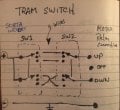
I can see how to wire two DPDT switches to allow either to reverse the direction (sketch below), but this circuit doesn't allow me to park it at "OFF" and restart in opposite direction from either level.

Any ideas on how to use relays or commonly available switches to do this?

Thanks - The way it is now means a lot of walking up and down to operate the tram!

TramSwitches.JPG
 
Top