Wiring 4 SPST to operate electric tab actuators

Thread Starter

813mariner

Joined Apr 2, 2019
7
Hello, brand new to this forum! Seems very informative and helpful. I have a fairly good background in wiring DC electronics especially marine applications but I am having a real hard time attempting to wire a project on my boat. Here's what i am trying to do:

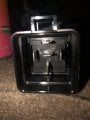
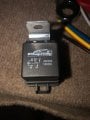
I have a custom switch panel with 4 single pole single throw switches. They will control electric trim tabs that stabilize the boat. The actuators have two wires on them (reverse polarity). I am trying to wire them so one switch deploys them and the other switch retracts them. 2 switches for each side of boat. The switches are only 3A , the actuators are rated 20A so plan on wiring them to a set of relays i have. I can always buy the factory switch which is two DPDT switches but they are so basic looking and this is a higher end project. I will attach pictures to help show what I have involved. Thank you!
 

Attachments

LesJones

Joined Jan 8, 2017
4,191
The switches in the picture look like push button switches. Are the contacts closed only while the button is pressed or does each press change the state between open and closed ? If the contacts are only closed while pressed then two SPDT relays (Like those in your picture.) for each side will do what you want. This would require the button to be held pressed for the full travel of the actuator. If you require just a short press to cause the full travel of the actuator then a bit more would be required. Also do the actuators have built in limit switches ?

Les.
 

Thread Starter

813mariner

Joined Apr 2, 2019
7
Les, the switches close the circuit when pressed, They are momentary, so as long as you press it in and hold it will activate the accesory. Not sure if the actuators have limit switches but they will only extend and retract to a certain limit. No short press for the full extend. Looking for on-demand response. Hold for 2 seconds, you get 2 seconds on the actuator, Either direction.
 

LesJones

Joined Jan 8, 2017
4,191
This should do what you want.

This will NOT prevent you from burning out the actuators if the button is held pressed when the actuator has reached the limit of it's travel. You can check if the actuators have limit switches by monitoring the current to the actuators. If the current increases when they reach the limit then they don't have limit switches. If it drops to zero then they do have limit switches. If they don't have limit switches you should find a way to fit them.Image020419.jpg
If both up and down buttons are pressed at the same time the actuator will stop. No damage will be done. The diodes are just to reduce sparking on the push button contacts. The circuit will work without them.
EDIT. I have just noticed the way I have drawn the motor will be connected to positive when no button is pressed. If you just swap over the NC and NO contacts on the relays the motor will be connected to negative when no button is pressed. (I am assuming a negative earth system.)

Les.
 
Last edited:

Tonyr1084

Joined Sep 24, 2015
7,905
Using the four SPST MOMENTARY switches you show, the diagram in LesJones' response (post #4) will be what you want. And as he edited, the positive should be connected to the NO contact as well.
 

SamR

Joined Mar 19, 2019
5,053
I would mount the power relays at the stern near the actuators and the battery. The control switches/buttons at the helm station of course. The 3A wiring is no problem. The 20A actuator power needs to be as short as possible or even use 24V actuators to cut down on amps if dual batteries are available.
 

Thread Starter

813mariner

Joined Apr 2, 2019
7
Thank you all for the responses! So let me see if I got this right from the drawings: i will connect my accesory wire from the switch to pin 87, 87A to motor leads, 86 & 85 to ground ?
 

Tonyr1084

Joined Sep 24, 2015
7,905
Thank you all for the responses! So let me see if I got this right from the drawings: i will connect my accesory wire from the switch to pin 87, 87A to motor leads, 86 & 85 to ground ?
No. That's not correct.

I have to step away for a shot time, but when I get back I'll post a drawing for you to follow.
 

LesJones

Joined Jan 8, 2017
4,191
Here is the schematic using your numbering system for the relay connections.
Image020419a.jpg
85 and 86 can be swapped over. (Make sure that the relays do not have a built in diode across the coil. If they do you will have to make sure that the cathode of the diode goes to positive.


Les.
 

Tonyr1084

Joined Sep 24, 2015
7,905
@LesJones beat me to it. Yes, pins 85 & 86 each are wired to each switch. You can wire them either way around because it's very likely your relays do not have flyback diodes in them. If they do, and I don't know one way or the other for sure, but if they DO have diodes in them then you have to make sure you put them the right way around. Each switch controls each relay. Each relay, pin 30 from each goes to the motor. Pins 87A go to ground and pins 87 (not 87A) go to battery power. If you still want a drawing, I'd be happy to bang one out for you.
 

Thread Starter

813mariner

Joined Apr 2, 2019
7
Tony, I am pretty sure they do have the fly back diode between 85 and 86. I was told on a different forum to get the relays with the diode’s because they will prolong the life of the push switches.
 

Tonyr1084

Joined Sep 24, 2015
7,905
OK, if your relays have flyback diodes on pins 85 & 86 then you need to determine exactly which way the diode is pointing. [edit] It has been determined that the diode cathode will be on pin 86 [end edit] It should be pointed at the positive side. In other words it looks like no current can pass through to ground. I've not included the diode in my drawing, and you may have to switch around the leads at 85 / 86 IF the diode is facing pin 86. This is just the way I've drawn it (as if the phantom diode is present) then the cathode is on pin 85. [edit] Drawing removed by self due to inaccurate information. See post #16 for corrected drawing. [end edit]
 
Last edited:

Tonyr1084

Joined Sep 24, 2015
7,905
According to @LesJones, the linked page states:

According to DIN 72552 the coil should be fed with +12V to terminal 86 and grounded via terminal 85, however in practice it makes no difference which way around they are wired, unless you are using a relay with an integrated diode (see more info on diodes below).

Therefore I have to amend my drawing to make it correct. Good news is that if your relays do not have a diode in them then even hooking it up the modified way won't harm anything. As it stands, if the diode is in the opposite position and you push the button you'll blow out the diode before the relay will work. Let's not do that. I'll post a new drawing in my next post.
 

Thread Starter

813mariner

Joined Apr 2, 2019
7
First dry run test of tabs everything looking good. it appears there are no limit switches on the actuators. The motors keep running when actuators are fully retracted and fully deployed.

I feel this shouldn’t be a huge issue as a slight change in the tab Angle causes noticable changes in how the boat rides thrugh the water, although without the limits, it might reduce the life of the actuators over time ?

Surprisingly enough, the automatic system That can be purchased seperately for this set of tabs has an auto retract feature when the key is turned to the acc. Position for 5 secs. as a safety feature, regardless of position. So if the tab is fully retracted to begin with, thats 5 seconds of run time with actuator bottomed out. Cant be good for them !
 
Top