Wireless power transfer project using 555 timer (having a problem with output voltage)

Thread Starter

Donaire Carapichoso

Joined Oct 15, 2019
9
Good day.

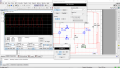
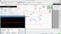
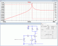
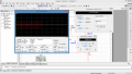
Well I am building a Wireless power transfer project for a final year project undergraduate degree.
Im using a 555 timer to generate the frequency and I would like to get at least 10V at the output of the coil L3 (thats for charging purposes)

I'm having the required resonant frequency and a proper sine wave but the voltage is to low (7mV to be specific).
I would like to know, how can I raise it.

Here is the circuit diagram, I'm using NI Multisim version 13.
And please find attached the file for the simulation (frequency, oscillation and the output voltage)
Thank you
upload_2019-10-15_9-59-15.png

Thank you
 

Attachments

AlbertHall

Joined Jun 4, 2014
12,345
The high value of R6 is restricting the collector current of Q2 to around 1mA.
Try reducing the value (a lot), but make sure that Q2 doesn't get too hot.
 

ericgibbs

Joined Jan 29, 2010
18,766
hi DC,
Welcome to AAC.
The constant current limit resistor R6 in the emitter of Q2 is limiting the current to less than 1mA
E
 

Thread Starter

Donaire Carapichoso

Joined Oct 15, 2019
9
hi.
Checking the resonant frequency with LTSpice I get this result.
What is your expected design freq at Resonance.?
E
Thank you
I would require any frequency in the ranges of 130 kz- Mhz
So the result you got is right, the only problem will be the voltage which is too low.

The impedance of the chosen capacitor and inductor at the resonant frequency is about 3Ω. Try the circuit with, say, 370uH and 4nF.
Yes, I have tried the above values and still the same voltage.
 
Last edited by a moderator:

Thread Starter

Donaire Carapichoso

Joined Oct 15, 2019
9
This circuit gives about 27V across L1.
Thanks a lot for your help, the voltage is has you said about 27V across L1... Thats is solved!!
As I'm not used to LTspice software, I'm finding a bit hard to perform the simulations (like to see the resonant frequency and so on).


Thank you :)

Your tuned circuit is resonant at 130Khz, you need to increase the Frequency of the 555 to match the resonance, change C2 to 1nF, remove the 1Mpot, set the 5K to half way..
Thank you , I have done that but no changes in the voltage as well.
 
Last edited by a moderator:

Thread Starter

Donaire Carapichoso

Joined Oct 15, 2019
9
Good day!!

Here I go again. I'm building a wireless power transfer system (final year project) and testing different circuits to get the clue of it.
I came across a circuit, but i am not sure the wave I have got is a proper for this system.
I was supposed to get a sine-wave but instead the wave is saturated (if im not wrong), I would like to correct it.

The circuit is as follow, and please find attached the screenshot for the simulation (showing the wave i am talking about)
Thank you...
upload_2019-10-19_19-57-50.png

MOD: Merged this post with your current Thread.E
 

Attachments

Last edited by a moderator:
Top