Facebook
 Google
 GitHub
 Linkedin
Hey Friends
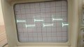
I'm creating wireless energy transfer circuit for that I'm using inverter circuit to generate 150 kHz square wave signal.I have attached the circuit diagram.When i assembled the circuit,I gave 12 V DC power supply.However at the output i got a square wave of 6 V max Voltage.This means there is voltage drop across the mosfets. Please note I have used Mosfet IRFZ44N in the circuit and not IRLZ44n.
Please tell me how to get a square voltage with 12v max voltage
I'm creating wireless energy transfer circuit for that I'm using inverter circuit to generate 150 kHz square wave signal.I have attached the circuit diagram.When i assembled the circuit,I gave 12 V DC power supply.However at the output i got a square wave of 6 V max Voltage.This means there is voltage drop across the mosfets.
Please note I have used Mosfet IRFZ44N in the circuit and not IRLZ44n.Please tell me how to get a square voltage with 12v max voltage