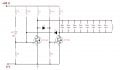
The first is a push-pull converter.
By the way. Diodes incorporated is not correct!
Need to change polarity.
The scheme works by using resonant circuit.
This path is radiating a magnetic antenna.
The second scheme consists of a resonant circuit and a bridge rectifier.
Resonant circuit must be set on the frequency of the first scheme.
Rectified voltage is supplied to the 5 volt regulator.
Transistors should work. When one transistor is turned on,
the second transistor must be closed.
This function is performed by diodes.
When one transistor is open at drain low voltage
and it is passed to the shutter the second transistor.
This second transistor because this will have a small gate voltage
(less than the threshold voltage).
Then the transistors are reversed.
Voltage fluctuations occur due to the presence of the oscillatory circuit (LC).
Hi,
Can u please explain how diodes perform that particular operation?..when the supply is given which diode will be forward biased and which will be reverse biased?what i know is if the positive terminal is connectd to postive and negative terminal connected to negative only then diodes will conduct....but hoe to determine whether they are forward biased or reverse biased?
Diodes pulled up at the gates to the negative terminal of the power supply (by turns). If you want a detailed understanding of the work of the scheme, the best way is the use of simulators. I recommend LTspice.
 Facebook
 Google
 GitHub
 Linkedin
 39.7 KB Views: 41
 7 KB Views: 33


