Facebook
 Google
 GitHub
 Linkedin
Hello All!
I am working on a project that requires a very small wireless charger. I need about 15mm outer diameter max on the reciever coil, and about 43mm minimum inner diameter or the transmitter coil. The design intent is for the device to charge while nested within the transmitter coil.
I don't need to transmit much power at all, only enough to charge a 70 mAh lipo in an hour or maybe 3.
Even 100 mW would be passable, 300 mW would be enough to charge the battery at its rated amperage, and 500 mW would be ideal so the device could operate while charging.
My transmitter coil is 20 turns. I have tried a wide range of receiver coils, varying from 10 to perhaps 100's of turns.
Please see the schematic attached below.
I originally hoped that I could increase the power transmitted simply by increasing the voltage on my transmission coil, however as the voltage is increased, the efficiency of the transfer decreases - even after re-adjusting the transmit frequency. I am operating at around 40-60 kHz.
There is a zener diode on the output of the rectifier to protect components from overvoltage.
Space is at a premium in this design.
Any ideas folks?
I can provide any part numbers or datasheets if required.
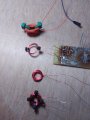
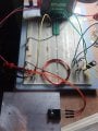
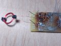
Or photos of my coils.
Thanks for your the help!
I am working on a project that requires a very small wireless charger. I need about 15mm outer diameter max on the reciever coil, and about 43mm minimum inner diameter or the transmitter coil. The design intent is for the device to charge while nested within the transmitter coil.
I don't need to transmit much power at all, only enough to charge a 70 mAh lipo in an hour or maybe 3.
Even 100 mW would be passable, 300 mW would be enough to charge the battery at its rated amperage, and 500 mW would be ideal so the device could operate while charging.
My transmitter coil is 20 turns. I have tried a wide range of receiver coils, varying from 10 to perhaps 100's of turns.
Please see the schematic attached below.
I originally hoped that I could increase the power transmitted simply by increasing the voltage on my transmission coil, however as the voltage is increased, the efficiency of the transfer decreases - even after re-adjusting the transmit frequency. I am operating at around 40-60 kHz.
There is a zener diode on the output of the rectifier to protect components from overvoltage.
Space is at a premium in this design.
Code:
| Input Voltage | Input Current | Input Power | Output Voltage | Output Current | Output Power  | Percent Efficiency |
|---------------|---------------|-------------|----------------|----------------|---------------|---------------------|
| 5             | 0.065         | 0.325       | 1.97           | 0.006116113    | 0.012048742   | 1.88
| 10            | 0.25          | 2.5         | 5.3            | 0.016454517    | 0.087208941   | 0.65
| 11.3 | 0.245 | 2.7685 | 6.2 | 0.019248680 | 0.11934181 | 0.69I can provide any part numbers or datasheets if required.
Or photos of my coils.
Thanks for your the help!
Attachments
-
 161.7 KB Views: 13
Last edited by a moderator: