 Facebook
 Google
 GitHub
 Linkedin
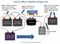
The attached diagram comes from this article: http://www.doityourselfrv.com/bring-van-camper-life-add-batteries-solenoid-stealth-rv/
Notice that the positive wires from the vehicle starting battery to the circuit breaker, and then to the continuous duty solenoid, and then to the aux (house) battery are specified as 10 AWG while the remaining main connections are specified as 2 or 4 AWG. I understand the importance of the large wire between the individual batteries in the aux battery bank, and also understand that the size of the wire to the inverter is dictated by the size of the inverter. I also plan to use 16 AWG wire from the fuse box to the solenoid.
What I am not completely convinced about is the 10 AWG wire. Please comment on that as well as any other parts of the diagram that pique your interest.
Thanks.
ETA: I will be traveling most of the day today, so don't be perturbed if I don't respond to your comments until tonight or tomorrow. Thanks.
Attachments
-
 177.1 KB Views: 5
Last edited:


