Wine cooler repair

Thread Starter

k.spence1190

Joined Aug 9, 2026
6
@MrChips

Hello, I saw your thread a while back about wine cooler repair and how to diagnose/repair the circuitry of the model I have. I am writing to you now to see if you might be able to help with wiring. I have a koldfront wine cooler twr187ess with a PCB121110K1. It is in perfect working order, I just took the hardware out to use on a different project. Any help would be greatly appreciated. If I have failed to include any pertinent info, I'll be more than happy to supply you with any info you might need

Moderators note : moved post from a non related thread.
 
Last edited by a moderator:

Thread Starter

k.spence1190

Joined Aug 9, 2026
6
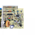
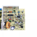
Does your board look something like this (one half of the board) ?

View attachment 370261

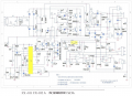
The schematics could be similar to this:

View attachment 370263
Yes sir. I have two of those boards for upper and lower electrothermal cooling unit. I am going to be honest, I don't understand how to read that schematic. I saw in your original post that you posted some photos of this exact board with the wires still attached. Do you have anything that shows all the wires attached or can you provide any information that a layman such as myself can decipher?
 

Thread Starter

k.spence1190

Joined Aug 9, 2026
6
if it is in working order, what is the problem? what kind of help you seek? how to put back what you took out? or need help carrying it to a dumpster? please specify...
I have taken the components out of the unit in an attempt to make an aquarium chiller. I thought I would be able to wire everything as it were but didn't account for my general forgetfulness
 

Thread Starter

k.spence1190

Joined Aug 9, 2026
6
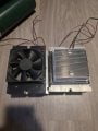
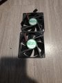
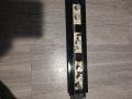
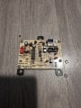
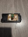
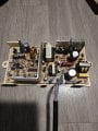
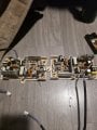
Here's all my components. I have salvaged all the connectors with the exception of the power supply to the thermoelectric cooling units which will have to be rewired
 

Attachments

MrChips

Joined Oct 2, 2009
35,003
CN1 on the left side of the board (not in photo) is AC power input. Brown = LINE, Blue = Neutral
CN2 = FAN2
CN3 = FAN1
CN4 = NTC1
CN5 = NCT2
P1 = +voltage to cooler
P2 = -voltage to cooler


1786319327162.png
 

Thread Starter

k.spence1190

Joined Aug 9, 2026
6
CN1 on the left side of the board (not in photo) is AC power input. Brown = LINE, Blue = Neutral
CN2 = FAN2
CN3 = FAN1
CN4 = NTC1
CN5 = NCT2
P1 = +voltage to cooler
P2 = -voltage to cooler


View attachment 370287
I have a few questions,
CN2 and CN3- I'm assuming these are the hot and cold side fans of the peltier module. Do you know which one is which?
CN4 CN5- which modules are these? Are they labeled CN4 and CN5 on The other board?

Is this the only board you have info on? The small board that I have pictured in picture five is pretty self-explanatory I think. That's 120 in then splits off the power both of the twin control boards in the last photo. As for the remaining board, is that just accessory components?
 
Top