Wilson Current Mirror

Thread Starter

Сергей999

Joined Jun 9, 2022
63
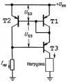
A change in the resistance in the collector T3 will result in a small change in the voltage at its base, which will lead to the same small change in the voltage at the collector T2. In T2, the Earley effect will appear, which will lead to a minuscule change in voltage already at its base, which will ultimately lead to a minuscule change in the collector current T3. So minuscule that practically the collector current T3 will not change in any way. It turns out that T3 does not get rid of the Earley effect, but only minimizes, right?
 

Attachments

WBahn

Joined Mar 31, 2012
32,702
Nothing you do can get rid of it entirely. The goal is to minimize it. So the real question isn't whether the Wilson mirror improves the situation, but by how much?

As for understanding the basic mechanism by which it accomplishes this, the reason that the Early effect causes a low output impedance is because as the Vce of the transistor changes, the current changes (at a constant Vbe) right?

So if we can hold Vce constant (or nearly so), the current won't change due to the Early effect because Vce isn't changing.

So understand how the Wilson current mirror circuit makes this happen.

To check your comprehension, consider that T3, like any other transistor, is subject to the Early effect and, as the load changes, it's Vce changes considerable. Why does this not result in corresponding changes in the output current?
 

crutschow

Joined Mar 14, 2008
38,316
Below is the LTspice sim of a standard two transistor current-mirror compared to a Wilson mirror:
Note that the Wilson output mirror current (blue trace) shows only a small change in current (≈2µA) for the change in V2 voltage (purple trace) compared to the standard mirror current (red trace) of about 85µA.

Any change in Q5's current due to the voltage change is minimized by the negative feedback through Q4.

1727666979467.png
 
Last edited:

WBahn

Joined Mar 31, 2012
32,702
That is, in a classical optical mirror there is an emitter feedback and in an intelligent Wilson mirror there is a collector feedback?
Classical optical mirror????

In the basic current mirror, there is no feedback at all.

The reference current source (often just a resistor) establishes a current in the input transistor, which is diode-connected (which I like to think of as the "projector"). This establishes the Vbe voltage on this transistor that corresponds to that current in the transistor at that Vce. The diode connection does invoke a feedback mechanism to hold the Vbe at this value, but that isn't what we usually think of as a feedback mechanism for the overall circuit.

That Vbe is then applied to the output transistor (what I like to think of as the "image" or "reflector" transistor). IF the Vce of that transistor is the same as the projector, then it will have the same current. But as Vce changes on the image transistor, there is no mechanism to compensate and so you get an output resistance that is simply the output resistance of the image transistor as dictated by the Early voltage.

But, in a Wilson mirror, small changes in the output current feedback into the projector side of the circuit. Note that the diode-connected transistor is in the image side of the circuit instead of the projector side.

Walk through what happens if the load changes in such a way that it would try to result in more current flowing in it (i.e., if it's resistance went down).
 

Bordodynov

Joined May 20, 2015
3,429
Wait, what about the resistor in the emitter? It is he who creates feedback and reduces the Earley effect... And a short-circuited transistor (diode) serves only for thermal compensation...
The transistor in the diode connection is still on the load in the emitter of the output transistor. Negative feedback from the collector of the first (input) transistor goes to the base of the output, then the emitter of the output transistor, or also to the transistor in the diode connection or the base of the input transistor.
That is, there is an OOS. And yes, the resistors in the emitters increase the output impedance of a conventional current mirror.
 

crutschow

Joined Mar 14, 2008
38,316
Why will the Earley effect on T2 be insignificant because of T1, is this unclear?
Because of T3, the voltage on T2 doesn't vary significantly.
So it's all about feedback?
That is, in a classical optical mirror there is an emitter feedback and in an intelligent Wilson mirror there is a collector feedback?
Any current change in T3, due to its collector voltage change, also changes the current in T1.
This then changes the current in T2 due to the mirror between the two, which adjusts the base voltage of T3 (negative feedback) to make the T3 current back to very near what it was.

1727717763469.png
 

WBahn

Joined Mar 31, 2012
32,702
Wait, what about the resistor in the emitter? It is he who creates feedback and reduces the Earley effect... And a short-circuited transistor (diode) serves only for thermal compensation...
That's not a basic current mirror, that's a current mirror with the addition of ballast resistors in the emitter paths, which provide a strong feedback signal into the system and greatly increase the output resistance as a result. They also serve to overcome the need for the transistors to be closely matched to get nearly the same current from both. In fact, you can use completely different transistors, say a small signal transistor for the projector and a power transistor for the reflector. You can also use them to scale the current nicely, so that your mirror has either gain or attenuation.

If you think that the diode-connected transistor is only there for thermal compensation, then you need to go back and learn how a current mirror works.

Key to this is forgetting about the notion of a BJT being a current-controlled device. It is a voltage-controlled device with the collector current being controlled by the base-emitter voltage.
 

Thread Starter

Сергей999

Joined Jun 9, 2022
63
There is an incomprehensible moment, the feedback loop includes the current of the emitter T3, but the collector current is not included? But after all, the emitter current is the collector current minus the base current, how strange is that!?
 

WBahn

Joined Mar 31, 2012
32,702
There is an incomprehensible moment, the feedback loop includes the current of the emitter T3, but the collector current is not included? But after all, the emitter current is the collector current minus the base current, how strange is that!?
Not strange at all -- it's called conservation of charge.
 

Thread Starter

Сергей999

Joined Jun 9, 2022
63
Key to this is forgetting about the notion of a BJT being a current-controlled device. It is a voltage-controlled device with the collector current being controlled by the base-emitter voltage.
I wonder if you suggest not thinking from the position of current, but from the position of voltage? There is a formula Ic=Ib*h21 which explains a lot, do you propose to rewrite it into voltage?
 

WBahn

Joined Mar 31, 2012
32,702
I wonder if you suggest not thinking from the position of current, but from the position of voltage? There is a formula Ic=Ib*h21 which explains a lot, do you propose to rewrite it into voltage?
Well, if you can come up with a way to mathematically describe how a basic current mirror works, even assuming perfectly-matched transistors, using that relationship, go for it.

Or, you can use the Ebers-Moll model, in which case describing how and why it works, becomes pretty trivial.
 

Thread Starter

Сергей999

Joined Jun 9, 2022
63
Let's start again from a position of tension. The resistance in the collector T3 has changed, the current in the emitter has not changed, the potential in the collector T2 has changed, which means that an Early appeared, BUT an important point is that the current in the emitter T3 has not changed, which means it has not changed in the collector T1, which means that the voltage Vbe T1 has not changed and as a result, T2 must change the current in the collector, which in turn it will change the potential of the collector, which means it will change the potential of the base T3 and accordingly change the current in the collector... That is, the important point of Vbe T1 does not change when the resistance in the collector T3 changes?
 
Last edited:

crutschow

Joined Mar 14, 2008
38,316
There is a formula Ic=Ib*h21 which explains a lot, do you propose to rewrite it into voltage?
No.
The h21 is a hybrid parameter which defines the current gain to determine collector current from the base current (basically the same as Beta).
This current control model is often useful for large signal analysis and bias calculations.

The physical model for the BJT shows it as a voltage-controlled device, which can be useful for small signal analysis (the base-emitter input voltage versus the collector current is defined as the transconductance (gm)).

The reason for the duality is that the base-emitter junction looks like a forward-biased diode, so you can look at the change in collector current as being proportional to the current-change through this junction, or proportional to the log of the voltage change across the junction which generates an exponential change in junction current.
 
Top