Why the second MOSFETs in a two-MOSFET series shorts?

Thread Starter

fablau

Joined May 14, 2020
167
Maybe you could connect the output of OPT3 across the gate/source of N1 (and eliminate N2) so it can prevent N1 turning on.
That's a great idea, but unfortunately, that is not possible at the moment because that part of the circuit is already printed and I should remake it completely to allow that. The current modularity of the whole system allows me to put some sort of "switch" only between the D6 and the drain of N1. But I'll keep that in mind in case I see no other options!
 

Thread Starter

fablau

Joined May 14, 2020
167
Any thoughts about why the N2 MOSFET shorts? I am getting crazy to figure that out. Thanks for any ideas!
 

Sensacell

Joined Jun 19, 2012
3,787
A helpful tip for making your schematics cleaner and easier to read:

Use ground symbols at all the points connected to ground, don't run a wire all over the diagram to show this connection.
 

Alec_t

Joined Sep 17, 2013
15,149
Any thoughts about why the N2 MOSFET shorts?
Guess 1: You have no spike suppression components across the inductive loads, so depending on your circuit layout a spike may be zapping N2.
Guess 2: We don't know the precise timing of your signals, but unless you have programmed some dead-time there may be shoot-through current killing the weakest/slowest FET.
 

Thread Starter

fablau

Joined May 14, 2020
167
Guess 1: You have no spike suppression components across the inductive loads, so depending on your circuit layout a spike may be zapping N2.
Guess 2: We don't know the precise timing of your signals, but unless you have programmed some dead-time there may be shoot-through current killing the weakest/slowest FET.
Thank you for your suggestions.

About the first guess, I am just wondering why I never had issues with just 1 MOSFET (N1) despite no spike suppression components being there. Also, I have added a flyback diode to protect N2, wouldn't that be sufficient?

About your second guess, how would you suggest managing "timings" to avoid that issue?

Thank you!
 

Thread Starter

fablau

Joined May 14, 2020
167
Depends upon how you connected the diode.
Does it go from MOSFET drain to V+?
I connected it from source to drain as shown in my first posted diagram (my first post on this thread).
Dear Musician,

thank you for your message.
at made no difference at all, the MOSFET shorted anyway.
 

crutschow

Joined Mar 14, 2008
38,669
I connected it from source to drain as shown in my first posted diagram (my first post on this thread)
Did you not read my previous post?
As I stated, that does nothing to protect the MOSFET.
The inductive transient generates a large positive voltage spike at the MOSFET drain, so how can a regular diode connected from source to drain protect against that?
made no difference at all, the MOSFET shorted anyway.
Of course not. How could it?
 
Last edited:

Thread Starter

fablau

Joined May 14, 2020
167
Whenever you switch off a FET, allow a couple of uS in your code before switching on another.
Ok, thank you. Fact is, during my tests, I opened N first, and after a few seconds opened N2. Then I opened/closed N1 several times, while N2 we still open, and after a few iterations, N2 shorted.
 

Thread Starter

fablau

Joined May 14, 2020
167
Did you not read my previous post?
As I stated, that does nothing to protect the MOSFET.
The inductive transient generates a large positive voltage spike at the MOSFET drain, so how can a regular diode to from source to drain protect against that?
Of course not. How could it?
Got it. Thank you for clarifying. It is my understanding then that the only way to protect both MOSFETs is to add the diodes around the coil as you suggested at post #10

I'll do that and try again. Thank you!
 

Thread Starter

fablau

Joined May 14, 2020
167
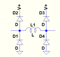
Actually, I'd need some help to understand exactly how to put those 4 diodes around the coil. You said:

A bidirectional coil can have the transients suppressed using four diodes.
Two go from each end of the coil V+ (cathode), and two go from each end of the coil to ground (anode).
But I can't figure out exactly how to wire those and I can't find any references around the web using 4 diodes (that's what I have currently to be able to test it). Any chances you could draw me a simple diagram to see how all that's wired around the coil?

Thank you!
 

crutschow

Joined Mar 14, 2008
38,669
I meant to add, the circuit will prevent any inductive spikes from going above more than one diode drop above V+, or one diode drop below ground.
 

Thread Starter

fablau

Joined May 14, 2020
167
Yes! Thank you so much @crutschow that fixed the problem! The MOSFET is no longer shorting :)

It's amazing how I could get away without those 4 diodes, now I see that it's been a sort of a miracle that other MOSFETs haven't shorted so far!

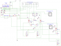
Here is the final diagram of the circuit with the 4 diodes added:

Sheet_3.png


And thanks also to @AnalogKid for his suggestion to use a bi-polar zener diode, I'll experiment with that as well:

https://forum.allaboutcircuits.com/...-two-mosfet-series-shorts.185593/post-1717110

And to anyone else who helped me. I really appreciated it.

Thanks to all of you, the problem is solved!
 
Top