Facebook
 Google
 GitHub
 Linkedin
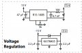
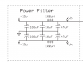
In many DC circuit i observe a power filter that applied that applied to filter the noise from DC circuit I don't understand why they are use? they are simple but my question is such power filter can really necessary or just use because in past power supply are more noisy? example figure attached
Attachments
-
 42.9 KB Views: 32