hi R77,
Welcome to AAC.
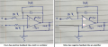
The Rfb resistor is incorrectly connected to the +Vin . it should be -Vin.
E.
Also you should have a resistor in series with the 3v3 zener.
The 3.3 V Zener there is a bad idea, even with a resistor.
1) The opamp will basically see a short when the output tries to push beyond 3.3V, this will cause maximum current/power dissipation and quick failure.
2) Zeners are not terribly accurate, the clamping voltage will not be very predictable.
3) Zeners don't typically have a super sharp threshold, they start to conduct more gradually than you might expect.
Reasons 1, 2 and 3 mean that even with a resistor to limit the current flow, the upper ADC values close to the threshold may become non-linear.
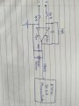
Use a simple diode/resistor to clamp the output voltage to the 3.3V rail, with an additional resistor before the ADC input to limit any current flowing into the MCU's input protection diodes.
Essentially the external diode is in parallel with the internal one, the extra resistor ensures that the external diode sees most of the clamp current.
This network will never conduct any current within the full ADC voltage range- no chance of non-linearity.
hi R77,
Welcome to AAC.
The Rfb resistor is incorrectly connected to the +Vin . it should be -Vin.
E.
Also you should have a resistor in series with the 3v3 zener.
hi R77,
Welcome to AAC.
The Rfb resistor is incorrectly connected to the +Vin . it should be -Vin.
E.
Also you should have a resistor in series with the 3v3 zener.
Its a DC input varying from 0 to 10V. As the output reach the 3.3 volt, processor is program to shutdown the particular part of the circuit. Hence I dont need output above 3.3V also it may damage the processor.
The 3.3 V Zener there is a bad idea, even with a resistor.
1) The opamp will basically see a short when the output tries to push beyond 3.3V, this will cause maximum current/power dissipation and quick failure.
2) Zeners are not terribly accurate, the clamping voltage will not be very predictable.
3) Zeners don't typically have a super sharp threshold, they start to conduct more gradually than you might expect.
Reasons 1, 2 and 3 mean that even with a resistor to limit the current flow, the upper ADC values close to the threshold may become non-linear.
Use a simple diode/resistor to clamp the output voltage to the 3.3V rail, with an additional resistor before the ADC input to limit any current flowing into the MCU's input protection diodes.
Essentially the external diode is in parallel with the internal one, the extra resistor ensures that the external diode sees most of the clamp current.
This network will never conduct any current within the full ADC voltage range- no chance of non-linearity.
has a floating antenna inductor attached to it ? e.g. no DC path to anywhere but -inp and output
your schematic doesnot define in unary understandable way
? are your inverting a and non-inverting op-Amp inputs corresponding to your labelling ←→ the capacitive feedback to non-inverting input would likely cause oscillation
Hi,
The resistor divider will affect the time needed for sampling by ADC, whereas op-amp will do so but to a significantly lesser degree. I want the output response as fast as possible.
Make 5V lable 3.3V, the diodes preferably schottky although most people using
small signal Silicon like 1N914, the 100 ohm more like 1 K ohm. That will protect input
to processor.
 Facebook
 Google
 GitHub
 Linkedin
 1.6 MB Views: 33