Why might a material have more traction on a smooth surface?

Thread Starter

strantor

Joined Oct 3, 2010
6,875
Maybe it will help if I explain why I am really so fixated on this. The example with the tire was actually a secondary realization but more easily conveyed so I used it to start the discussion. The real issue is when extruding the material. I have been working on designing a new hotend which is better for super flexible filaments. I have been testing ordinary 95A TPU, as well as 30D (~78A), 75A, and 60A filaments.

I am using an OmniaDrop extruder which is renowned for its performance with flexible filaments and spent most of my efforts on optimizing the hotend. I have gone through at least a dozen hotends, some of the most highly rated commercially available ones but mostly those of my own design. Among the commercially available ones, the "serious" hotends and nozzles have a Ra roughness spec. The smoother the bore, the better, supposedly. So among those I have designed, I was initially trying to polish the bore as sooth as possible. I even went so far as to build a hotend which was entirely lined with PTFE all the way from the bottom of the extruder gears to the tip of the nozzle. I bought high quality precision reamers and produced barrels with mirror finish inside. It seemed there was not much that could be done to improve the flow through the hotend.

I had one barrel which I had made from scratch early in the process, drilled through solid rod with a poor quality 2mm drill bit, and the interior surface was not very smooth. It was a fly in the data ointment as it outperformed everything I had tested by 5%. I bought some needle eye barrel laps and lapping compound and lapped another barrel. I did something wrong when lapping, not sure what, but the result was a barrel bore that had a finish like micro-scale "orange peel" in a bad automotive paint job. I almost didn't even test it because it was a "failure" but decided "what the heck, if I can't get numbers to stand out positively, I'll make them stand out negatively. At least that will tell me if I'm barking up the right tree with regards to barrel finish." So I tested it and the results were very counterintuitive. It outperformed all previous tests by 20%. So I tested a barrel in which I had intentionally destroyed the surface finish by running through it with a drill holding a bristle I made from fine stainless wire. It had deep scratches all through it from one end to the other and it performed about the same as the orange peel barrel. So now the trend indicates that a rough barrel, not a smooth one, improves flow through the hotend.

I have entertained several theories about why this is, and the two I feel best about are:
1. that the rough barrel creates turbulent flow which mixes hotter material with cooler material, pulling cooler material from the center out to the walls, and results in a more evenly heated fluid at the nozzle. And,
2. that there is some microscopic tractive interaction between a smooth filament and a smooth bore, which is not present (or less present) with a rough bore.

I think it likely that there are multiple reasons, including the two above, but I am almost entirely convinced that #2 IS happening, and is one of the greatest contributing factors, because I was able to squeeze a bit more performance out of the system by ditching my PTFE-lined heatbreak for an all-metal one whose bore I had scratched up with carbide. So this is not just a fluid flow phenomenon, it applies to the unmelted filament prior to entering the melt zone.

I want to understand what is going on here so that I can further optimize the design. Is there maybe a specific pattern which would give better results? A certain depth of scratches? Understanding why I hope would lead to how to do it intentionally.

Also I would like to know why PTFE-lined heatbreaks and smooth bore nozzles are the default suggestions to anyone wanting to print flexible filaments. Is this all born from a bad assumption and reinforced by monkey see, monkey do? Has nobody actually tried going against conventional wisdom? I mean, yeah it seems totally intuitive that "smoother the better" but I have a wealth of data proving that false.
 

Thread Starter

strantor

Joined Oct 3, 2010
6,875
I am assuming that you have seen this design? It is designed for high flow, and does achieve that.

Yes I have tested several CHT designs. They do improve flow over a standard nozzle, in a standard hotend, but I think they are a workaround for a bigger problem that very few people seem to acknowledge. We are (with a standard hotend) trying to "zap" ambient temperature plastic into a molten state within an insufficient window of time spent in a laughably tiny melt zone. The best most of us can manage is to make the filament soft enough to brute force through a tiny nozzle, and it isn't truly melted (liquefied).

I have found that if you increase the length of the melt zone, you can run much faster for the same amount of time the filament spends in the melt zone. And if you further increase the melt zone (beyond the X/Y linear mm/s capability of your printer) then you can haul buns AND the filament comes out actually melted. You get better layer adhesion and the extruder doesn't have to work as hard. When the filament is an actual fluid before it reaches the nozzle, it wants to come out, and the extruder just gives it permission. If you're concerned about the weight of a long melt zone, consider that when you're not brutally force feeding the hotend, you don't need such a huge extruder motor. What weight you add in the hotend can be subtracted with a smaller motor.

The 3D printing community in general, by my estimate, considers 20mm³/s volumetric flow to be about on the high side of normal, 30mm³/s to be excellent, and 50mm³/s to be the end of the known universe. I am printing 123mm³/s in PLA and 112mm³/s in 95A TPU. With the 60A and 30D filament though, I haven't been able to realize such drastic improvements. 60A in my stock extruder tops out around 3mm³/s before it wraps itself around the gears. The best I have gotten out of any of my designs is 7mm³/s. For 30D, I was able to get 12mm³/s stock and 20mm³/s with my design. I really want to be able to print these super flexibles at a respectable speed.

When I used a CHT nozzle in one of my hotends, the performance went down slightly. I think because the filament was already liquefied before it hit the nozzle, the CHT insert had no job to do, and was just a restriction in the flow path of the fluid.
 

LowQCab

Joined Nov 6, 2012
5,101
A hole with a rough-surface has more "Surface-Area" for transferring Heat,
and the resultant "more-turbulent-flow" may also assist in more-even-heat-transfer to the material.

Just a couple of off-hand guesses.
.
.
.
 

Ya’akov

Joined Jan 27, 2019
10,262
You know, thinking about your problem I think you aren’t dealing with friction, rather with adhesion.

It seems that polymers will adhere to smooth surfaces more readily than to surfaces with (relatively) large features. While friction on a polished surface may be reduced, the electrochemical bonding of the polymer seems to increase.

I am not certain I have this right, but there are some papers on it, and it seems to follow the intuition that made me look for it.
 

Ya’akov

Joined Jan 27, 2019
10,262
Also, I had been thinking about the idea of pre-heating the filament to just below the vitrification temperature just inside the heat break. This would not harm the filament outside the heat break, but I think it might make bringing the filament in the hot end up to printing temperatures easier.
 

Thread Starter

strantor

Joined Oct 3, 2010
6,875
Also, I had been thinking about the idea of pre-heating the filament to just below the vitrification temperature just inside the heat break. This would not harm the filament outside the heat break, but I think it might make bringing the filament in the hot end up to printing temperatures easier.
I tried that on suggestion from others and, while my attempt probably wasn't 100% the ideal test of the theory, it didn't pan out. A previous version of the hotend had 3 "volcano"-sized heaters in series (physically, not electrically), with 3 separate heating outputs, 3 separate temperature signal inputs, and 3 separate PID loops, just like an industrial multi-zone extruder. To test the "preheating" concept I just disabled the top heater. Still, a lot of heat from the bottom and middle heaters made its way upwards and the temperature at the top of the stack was only 20-30 degrees cooler than the bottom two. The result was worse than having just two heaters. I think the softened-but-not-melted filament just lost what little spine it had, and with it, its ability to push out whatever is underneath it.

You know, thinking about your problem I think you aren’t dealing with friction, rather with adhesion.

It seems that polymers will adhere to smooth surfaces more readily than to surfaces with (relatively) large features. While friction on a polished surface may be reduced, the electrochemical bonding of the polymer seems to increase.

I am not certain I have this right, but there are some papers on it, and it seems to follow the intuition that made me look for it.
I think you are on to something. Thank you, and I am sure that I will be doing a deep dive on this topic tonight while I should be sleeping.
 

Thread Starter

strantor

Joined Oct 3, 2010
6,875
A hole with a rough-surface has more "Surface-Area" for transferring Heat,
and the resultant "more-turbulent-flow" may also assist in more-even-heat-transfer to the material.

Just a couple of off-hand guesses.
.
.
.
Yes I suspect both of those things are also at play here.
 

Thread Starter

strantor

Joined Oct 3, 2010
6,875
You know, thinking about your problem I think you aren’t dealing with friction, rather with adhesion.

It seems that polymers will adhere to smooth surfaces more readily than to surfaces with (relatively) large features. While friction on a polished surface may be reduced, the electrochemical bonding of the polymer seems to increase.

I am not certain I have this right, but there are some papers on it, and it seems to follow the intuition that made me look for it.
Well I have taken the first steps into the rabbit hole of the tribological properties thermoplastic elastomers. I have read several research papers and found confirmation of my suspicion that there is some spooky stuff going on at the atomic level. I learned that:
  • Yes, adhesion plays a big part in it
  • Yes, TPU and other TPEs have an inverse relationship of coefficient of friction and the roughness of the mating material.
  • TPU actually has a higher coefficient of friction than nitrile rubber against something extremely smooth like a chromed hydraulic cylinder rod. (*)
  • The 3 previous points are all false. Or could be, depending on the specific TPU you are using. There are several different kinds of TPE and many different additives that might be present in them, resulting in probably thousands of different variants with wildly different properties, all sold as "TPU." I have tested some other TPU filaments that didn't have this issue, now I know why.
  • The coefficient of friction of TPU increases with speed and also increases with temperature, so the heatbreak of a 3D printer suffers a double-whammy. Or a triple-whammy if you're like me and insist on using the stuff that clings to smooth metal because it makes tires that suck less for driving across smooth metal.
* Or at least it did for the specific TPU chosen by the authors of the paper "Thermal analysis and tribological investigation on TPU and NBR elastomers applied to sealing applications"

So I think that the conventional wisdom of "the smoother the better" probably isn't just an untested bad assumption. It is probably the right call for what anyone might consider "normal" TPU, or was once upon a time the right call for most/all TPU sold as 3d printer filament, but not anymore, not for all TPUs.

I think the deck is stacked against me for designing a hotend that will print my TPU fast. I should just consider my hotend a win since it works well for other filaments, and choose a different go-to TPU, there are plenty of options. The only reason I haven't done that already is that I've tested 15 TPUs and only got one that made a decent tire. Who knows how much more testing will be required to find the next one? It feels like a guaranteed nightmare.
 

Thread Starter

strantor

Joined Oct 3, 2010
6,875
Ceramics?
Interesting question, why do you ask? Have you found ceramics to have less stiction with similar materials?

On your prompt I went and rubbed all the ceramics I could find, which wasn't much (TIG torch cups, ceramic heater core, light bulb base) against the filament and against some printed tires, and my unscientific testing indicates that there is a higher coefficient of friction between TPU and ceramic, than between TPU and polished metal. I don't know if this is just at room temperature and maybe it's a different story at/beyond the melting temperature? Do you think it's worth the time and money to get a hotend barrel cerakoted for testing?
 

Ya’akov

Joined Jan 27, 2019
10,262
Interesting question, why do you ask? Have you found ceramics to have less stiction with similar materials?

On your prompt I went and rubbed all the ceramics I could find, which wasn't much (TIG torch cups, ceramic heater core, light bulb base) against the filament and against some printed tires, and my unscientific testing indicates that there is a higher coefficient of friction between TPU and ceramic, than between TPU and polished metal. I don't know if this is just at room temperature and maybe it's a different story at/beyond the melting temperature? Do you think it's worth the time and money to get a hotend barrel cerakoted for testing?
Well, the reason it came up is because I would expect that ceramics (non-metallic) could have very different surface energies than metals. If adhesion is the problem, surface energy will be critical. I would expect there is some material out there that would be better suited from an adhesion standpoint but I am not sure that it would also have sufficient thermal resistance.

There's a weird polymer that's a combination of PEEK and TPFE that has exceptionally low friction, and it's good for use at 260°C, and can tolerate higher temps for short times. It can be machined... I don't know if it offers an advantage and I am guessing it doesn't come cheap.

Anyway, I really don't know enough about surface energy to know which materials are particularly low in it. I feel that's a potentially fruitful direction.
 

Thread Starter

strantor

Joined Oct 3, 2010
6,875
Well, the reason it came up is because I would expect that ceramics (non-metallic) could have very different surface energies than metals. If adhesion is the problem, surface energy will be critical. I would expect there is some material out there that would be better suited from an adhesion standpoint but I am not sure that it would also have sufficient thermal resistance.
Maybe some mineral like ruby, sapphire, quartz? They all seem like things that it would want to stick to, but I am pretty much done making assumptions about this stuff; nothing would surprise me at this point.

There's a weird polymer that's a combination of PEEK and TPFE that has exceptionally low friction, and it's good for use at 260°C, and can tolerate higher temps for short times. It can be machined... I don't know if it offers an advantage and I am guessing it doesn't come cheap.
I think you might be referring to PEEKsil tubing. I looked into that a while back when I was dreaming up a bowden extruder where the tube carries molten plastic instead of filament. I don't know that if in this case it would offer any advantage over plain-ol PTFE tubing (also rated 260C), of which I have already tried lining the barrel with, all the way through the heat brake to the nozzle.

Anyway, I really don't know enough about surface energy to know which materials are particularly low in it. I feel that's a potentially fruitful direction.
You're probably right.

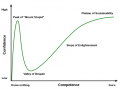
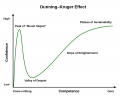
For now I am abandoning this in favor of finding a more friendly filament that makes a decent tire. If that proves harder than all this and it becomes apparent that I will have to pick up where I left off, I will let this page serve as my notes to refer back to. Thank you for your help. You guided me to the peak of mount stupid and I just don't have time for the trip into the valley.
1713386433553.png
 

Attachments

Ya’akov

Joined Jan 27, 2019
10,262
Maybe some mineral like ruby, sapphire, quartz?
Minerals, ceramics, other polymers—something other than metals I'd expect.

I think you might be referring to PEEKsil tubing.
No, it's called TECAPEEK. Pretty amazing stuff, actually.

For now I am abandoning this in favor of finding a more friendly filament that makes a decent tire.
Sounds like a good idea, it would be nice if you have the chance to write up the search a bit. I've had mixed results with TPU, but I really like it. I normally print with my Bambu Lab X1 Carbon but I had an Ender 3 Neo with a direct extruder that might be better in some ways. It's with my son right now, but I might grab it for experiments.
 

Thread Starter

strantor

Joined Oct 3, 2010
6,875
it would be nice if you have the chance to write up the search a bit.
Not sure what you mean. Like links to the studies I read?
I've had mixed results with TPU, but I really like it. I normally print with my Bambu Lab X1 Carbon but I had an Ender 3 Neo with a direct extruder that might be better in some ways. It's with my son right now, but I might grab it for experiments.
If you're a fan of TPU you might want to check out Overture High Speed TPU. It's become my go-to for anything TPU that isn't tires because I can't stand printing in turtle mode. Your Bambu will probably be able to print it faster than the 32mm³/s that it's rated for. Parts made from it are indestructible and look good. Consistent results, hasn't let me down.
 

Ya’akov

Joined Jan 27, 2019
10,262
Not sure what you mean. Like links to the studies I read?

I meant your struggle to find the best printing TPU, the profiles you develop, and how to source it.
If you're a fan of TPU you might want to check out Overture High Speed TPU. It's become my go-to for anything TPU that isn't tires because I can't stand printing in turtle mode. Your Bambu will probably be able to print it faster than the 32mm³/s that it's rated for. Parts made from it are indestructible and look good. Consistent results, hasn't let me down.
Noted—I will investigate that. Thanks!
 

Thread Starter

strantor

Joined Oct 3, 2010
6,875
I just had an eye opening conversation; someone on Discord was discussing their idea to use a high voltage to cause an electrostatic attraction of the filament to the bed. That took me down a rabbit hole, where I learned that their concept might actually not be nonsense, and that my extrusion problem might actually be related. You suggested adhesion as the cause, as opposed to friction, and for the last 4 months I have been operating under the assumption that you are correct. "the filament is just sticky" was a good enough explanation for me. But this guy on Discord was saying that tape adhesive works by this electrostatic principle. I think he is wrong about that, but I did google it regardless and found this:
https://en.wikipedia.org/wiki/Electroadhesion
Electroadhesion[1] is the electrostatic effect of astriction between two surfaces subjected to an electrical field. Applications include the retention of paper on plotter surfaces, astrictive robotic prehension (electrostatic grippers), electroadhesive displays,[2] etc. Clamping pressures in the range of 0.5 to 1.5 N/cm2 (0.8 to 2.3 psi) have been claimed.[3] Currently, the maximum lateral pressure achievable through electroadhesion is 85.6 N/cm2.[4]
So apparently if you really want to go out of your way to do it, you can use an electrostatic charge to apply up to 125PSI of pressure to a surface.
So then how much force could be attributed to naturally occurring (unwanted) electroadhesion?
I am almost convinced that this is actually happening to some extent. Often my printer builds up a static charge and I get zapped when I touch it. I noticed months ago that it only happens while printing, didn't think much of it until now. I also notice now that the static zaps are more energetic and occur more frequently when printing these problematic TPEs.
At work I deal with the pneumatic conveyance of plastic pellets and I see them all the time, sticking to the walls of metal silos and railcars by static attraction.
So I now strongly suspect that (probably not all, but some of) the problem is electroadhesion. The filament is statically clinging to the inside of the bore as it moves through.
So, what to do about it? I don't understand static electricity, never have. It is magic to me. Are there any static canceling spells I can cast at it?
At work one time we tested these anti-static guns that somehow shoot ("rays?") of ("not-static?") at surfaces to make them release whatever it statically clung to them. They sorta worked.
Can I maybe run the filament over a high voltage pulley or something to "pre-treat" it before going into the extruder? deliberately impart some charge on that will cause it to be repelled from the bore of the hotend instead of attracted to it? If so, how would I do that?
One of the things I don't understand about static is the reference point to which it is measured. It seems like it is relative to ground (earth) but why? Planes get static buildup when they're nowhere near the ground, and.... you know what, never mind. One thing at a time.
Statically charging the filament prior to extrusion? Yea or nay? if so, how? AC or DC? connected between where and where?
Other ideas?
Do I sound deranged? Am I chasing fairies? Is there a better explanation?


EDIT: This might explain why there seems to be a "speed limit" on these materials that simply can't be exceeded no matter how much surface area you have in the hotend, or how hot you run, or how much grunt your extruder has. MAybe the faster you push the the filament, the more static it generates, so the harder it clings to the walls. And that is exactly how I have described it, maybe not here, but I have discussed it many time and it really does seem that the harder you push it, the harder it pushes back! This makes too much sense! (So it's probably wrong.)
 
Last edited:

nsaspook

Joined Aug 27, 2009
16,363
No, your reasoning is good. There are electrostatic motors of various types.
https://en.wikipedia.org/wiki/Franklin's_electrostatic_machine

Ground is simply a reference with more or less charge than the other point in the electrostatic circuit. With a proper electrostatic motor controller the 'ground' switches to optimize rotation.

https://spectrum.ieee.org/electrostatic-motor
Electrostatic Motors Reach the Macro Scale
Such advantages prompted Ludois to cofound a company, C-Motive Technologies, to build macro-scale electrostatic motors. “We make our machines out of aluminum and plastic or fiberglass,” he says. Their current prototype is capable of delivering torque as high as 18 newton meters and power at 360 watts (0.5 horsepower)—characteristics they claim are “the highest torque and power measurements for any rotating electrostatic machine.”
 

Ya’akov

Joined Jan 27, 2019
10,262
No, your reasoning is good. There are electrostatic motors of various types.
https://en.wikipedia.org/wiki/Franklin's_electrostatic_machine

Ground is simply a reference with more or less charge than the other point in the electrostatic circuit. With a proper electrostatic motor controller the 'ground' switches to optimize rotation.

https://spectrum.ieee.org/electrostatic-motor
Electrostatic Motors Reach the Macro Scale
The apparatus in the rear is an electrostatic motor I built for this VDG prominently in the front when I was working at a science museum. The rotor is a plexiglass disc (the colors are vinyl to make the rotation visible) that is locally charged by an electrode causing it to be repelled by copper plane behind and the only way to go is rotary so it spins and another electrode discharges the disk as it goes by so it can be charged again.

My set up was very inefficient—it was just a demo.

IMG_3292.jpeg
 

nsaspook

Joined Aug 27, 2009
16,363
The apparatus in the rear is an electrostatic motor I built for this VDG prominently in the front when I was working at a science museum. The rotor is a plexiglass disc (the colors are vinyl to make the rotation visible) that is locally charged by an electrode causing it to be repelled by copper plane behind and the only way to go is rotary so it spins and another electrode discharges the disk as it goes by so it can be charged again.

My set up was very inefficient—it was just a demo.

That's been the problem with larger devices. The Coulomb force is incredibly strong at short distances but the ability to electrically separate motor drive plates at distances that increase efficiency has been a long term problem with larger more power devices.
https://energyeducation.ca/encyclopedia/Coulomb's_law

The trick is engineering a practical device. The C-Motive device is pretty slick even if it's unlikely to replace most magnetic force motors.
The machine would be feeble if the dielectric between the charges was air. As a dielectric, air has low permittivity, meaning that an electric field in air can not store much energy. Air also has a relatively low breakdown field strength, meaning that air can support only a fairly weak electric field before it breaks down and conducts current in a blazing arc. So one of the team’s greatest challenges was producing a dielectric fluid that has a much higher permittivity and breakdown field strength than air, and that was also environmentally friendly and nontoxic. To minimize friction, this fluid also had to have very low viscosity, because the rotors would be spinning in it. A dielectric with high permittivity concentrates the electric field between oppositely charged electrodes, enabling greater energy to be stored in the space between them. After screening hundreds of candidates over several years, the C-Motive team succeeded in producing an organic liquid dielectric with low viscosity and a relative permittivity in the low 20s. For comparison, the relative permittivity of air is 1.

Another challenge was supplying the 2,000 volts their machine needs to operate. High voltages are necessary to create the intense electric fields between the rotors and stators. To precisely control these fields, C-Motive was able to take advantage of the availability of inexpensive and stupendously capable power electronics, according to Ludois. For their most recent motor, they developed a drive system based on readily available 4.5-kilovolt insulated-gate bipolar transistors, but the rate of advancement in power semiconductors means they have many attractive choices here, and will have even more in the near future.
 
Top