why LED current fliping in negative direction in LT spice simulation?

Thread Starter

meena udayasankar

Joined Mar 29, 2017
14
Hi,

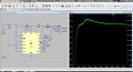
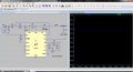
I am trying boost converter using LT3517 with 5V input. LED and input current(5V) is constant for our application. I need to tune the circuit between this and the current across the LED should be 500mA as per our application. so I put 1.65 ohms current sense resistor.
But 5V input is not switching . can i know the reason for it?

what is the mistake i made in the below circuit?
How can I boost the voltage?

Thanks in advance
 

Attachments

crutschow

Joined Mar 14, 2008
34,468
Here's my simulation, modified per this circuit from the data sheet:
R1 needs to be about 200mΩ for 500mA LED current.
Note that the simulation is very slow and took several minutes for the results shown.
Also Q1 is only needed if you want to use the PWM input.

upload_2017-4-3_11-30-21.png

upload_2017-4-3_14-39-4.png
 

Attachments

Last edited:

Thread Starter

meena udayasankar

Joined Mar 29, 2017
14
Hi,

Thanks.. but the negative terminal of the LED and capacitor will go to ground right.. Am I correct?

How the 3.92meg and 124K will act in the above circuit? As per the datasheet, the boosting calculations formula is,
(R4/R5+1)*1.01V.

I got 32V output. How this 32V plays a role in input voltage?

Thanks in advance
Here's my simulation, modified per this circuit from the data sheet:
R1 needs to be about 200mΩ for 500mA LED current.
Note that the simulation is very slow and took several minutes for the results shown.
Also Q1 is only needed if you want to use the PWM input.

View attachment 123890

View attachment 123901
Hi,

In the datasheet , they gave different configuration for boost converter. The one I uploaded before is demo circuit which I downloaded in LT...
Which one is preferable to use? the demo circuit or the circuit in datasheet?

I also tried the circuit in datasheet with 5v input and 500mA current. But I got 6.27V(7V is required in our case) and output is 258mA current.

I am a beginner .kindly guide me to take further steps.

Thanks in advance..
 

crutschow

Joined Mar 14, 2008
34,468
In the datasheet , they gave different configuration for boost converter. The one I uploaded before is demo circuit which I downloaded in LT...
Which one is preferable to use? the demo circuit or the circuit in datasheet?

I also tried the circuit in datasheet with 5v input and 500mA current. But I got 6.27V(7V is required in our case) and output is 258mA current.
The circuit I posted was a buck-boost circuit from the data sheet.
Since you don't need a buck function, you can ground the LEDs.

The reason you are only getting 258mA through the LED is because your circuit is monitoring the current through the inductor, not the LED and, for a boost converter, the inductor current is greater than the LED current (see simulation).
My circuit monitors the current through the LED.

Here's my circuit modified with the LED to ground, along with some other changes to make it more similar to your circuit.

The LED current is 500mA as you wanted.

The LED voltage is whatever the LEDs need at 500mA, which for the LEDs simulated, is 6.7V @ 500mA.
Remember, you can control voltage or you can control current, but you can't control both at the same time. :rolleyes:

upload_2017-4-3_23-45-35.png
 

Attachments

Last edited:
Top