 Facebook
 Google
 GitHub
 Linkedin
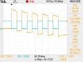
In the figure ,square wave is passed through 1uf capacitor .in the beginning of the wave is intact but later it becomes biphasic, ie it starts to dip into negative value.can someone explain this behavior?
Attachments
-
 91.7 KB Views: 34


