Facebook
 Google
 GitHub
 Linkedin
So I have a DPDT Switch that I want to connect to a motor in order to be able to switch its polarity and turn it off.
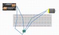
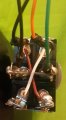
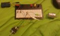
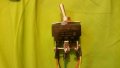
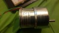
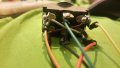
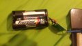
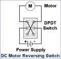
The model of the switch is MCR13-28E-01 and I'm using a 3V battery energy source. I've done exactly as instructed in all the DPDT online guides (images attached of everything I've just described)
But, it doesn't work. If I connect it without the toggle switch, it works (it rotates slowly, but it does work).
What can it be? The DPDT switch is brand new.... and I know it works because when I try to connect it as just a switch (not in order to reverse polarity) it works as a regular switch
Attachments
-
 88.4 KB Views: 38
 -
 95.5 KB Views: 38
 -
 113.5 KB Views: 39
 -
 102.3 KB Views: 38
 -
 41.4 KB Views: 100

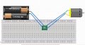
") even then it was all chalkboard and nothing practical so I'm struggling in converting diagram to real life. Could you please show me how the connection would look like on a breadboard?
even then it was all chalkboard and nothing practical so I'm struggling in converting diagram to real life. Could you please show me how the connection would look like on a breadboard?