Facebook
 Google
 GitHub
 Linkedin
Hello!
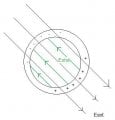
This is a matter that I have never understood. Inside a conductor (the shield in this case) there is not supposed to be any electrical field. If there was, the charges on the conductor would move in order to balance it, making it zero on the inside. So, it is perfectly understandable that using a shield will reduce the noise. However, why is it important to ground it??
This is a matter that I have never understood. Inside a conductor (the shield in this case) there is not supposed to be any electrical field. If there was, the charges on the conductor would move in order to balance it, making it zero on the inside. So, it is perfectly understandable that using a shield will reduce the noise. However, why is it important to ground it??