Hi All,
This isn't a homework question, I'm a software engineer starting to teach myself about circuits but I figured this would be the most suitable place to post given my serious lack of knowledge.
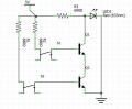
I created a NAND gate which I've pasted below. When I activate the right-hand button the led brightness increases. Activating both turns off the LED as expected and activating the left button doesn't alter the LED brightness. In case it's hard to make out the +5v goes to the collector of the top transistor and the emitter of this transistor feeds into the collector of the second transistor whose emitter is in turn connected to ground.
I understand that resistors in parallel reduces the effective resistance in a circuit but I don't see how the circuit is being activated in this case when the right button is being pressed. If the emitter of the top transistor were attached to ground it would make sense to me, however with the emitter going to the collector of an un-activated transistor I don't see how the circuit for the right button would create any potential difference to supply additional voltage to the LED as the trace would go +5v -> resistor -> button -> transistor base -> transistor emitter -> transistor collector -> stop. I've measured across the led and there's an additional .1v - .2v when the right button is pressed

This isn't a homework question, I'm a software engineer starting to teach myself about circuits but I figured this would be the most suitable place to post given my serious lack of knowledge.
I created a NAND gate which I've pasted below. When I activate the right-hand button the led brightness increases. Activating both turns off the LED as expected and activating the left button doesn't alter the LED brightness. In case it's hard to make out the +5v goes to the collector of the top transistor and the emitter of this transistor feeds into the collector of the second transistor whose emitter is in turn connected to ground.
I understand that resistors in parallel reduces the effective resistance in a circuit but I don't see how the circuit is being activated in this case when the right button is being pressed. If the emitter of the top transistor were attached to ground it would make sense to me, however with the emitter going to the collector of an un-activated transistor I don't see how the circuit for the right button would create any potential difference to supply additional voltage to the LED as the trace would go +5v -> resistor -> button -> transistor base -> transistor emitter -> transistor collector -> stop. I've measured across the led and there's an additional .1v - .2v when the right button is pressed