Facebook
 Google
 GitHub
 Linkedin
When I connected 2 diodes (30A) in parallel, the current was flowing only through only one of them. Why didn't it flow through both?
My input source is 2 solar pannels (550W each) connected in parallel (each panel is protected with the same kind of diode (30A) at the roof).
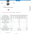
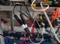
I feed this input (that would be 43V , 25A current for both panels) into 50A step down module, which outputs 29.2 V . The output wires of the step down module I route it through two 30A diodes (which I borrowed from solar panel installation) before they go into the BMS. The BMS will make the current on the bus to flow both directions, so I have to put a diode to prevent backflow (otherwise the buck converter will burn), but since i don't have 50A diode (or bigger) I decided to wire the diodes in parallel. 30A + 30A = 60A, I thought it was enough. (See attached picture for reference)
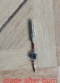
Now, when measuring the current with clamp ampere-meter I notices that current (25A at the time of measurement) was flowing only through one of them, the other was getting somewhere like 400 milliamps of current or so. Then the diode that was doing all the work broke (I heard the "click" sound) and it smelled like smoke was going, I checked with clamp meter and the diode had 0 current, but at the same time, the other diode entered to work, and I was seeing the same 25A current flowing . So, first diode burned, the second diode entered operation immediately.
According from what I have read about Kirchhoff's Law, if I have a node with 1 input and 2 outputs, the current must be flowing both sides, a portion of current will flow on one wire, the other portion will flow on another. Why didn't this happen in my case??? Yes, I can understand that maybe wire will get 10amps, another will get 15 because they have different resistance. But 0 amps on one wire and the other one burning??? This is very weird to me.
How do I make it so current flows both wires ?
My input source is 2 solar pannels (550W each) connected in parallel (each panel is protected with the same kind of diode (30A) at the roof).
I feed this input (that would be 43V , 25A current for both panels) into 50A step down module, which outputs 29.2 V . The output wires of the step down module I route it through two 30A diodes (which I borrowed from solar panel installation) before they go into the BMS. The BMS will make the current on the bus to flow both directions, so I have to put a diode to prevent backflow (otherwise the buck converter will burn), but since i don't have 50A diode (or bigger) I decided to wire the diodes in parallel. 30A + 30A = 60A, I thought it was enough. (See attached picture for reference)
Now, when measuring the current with clamp ampere-meter I notices that current (25A at the time of measurement) was flowing only through one of them, the other was getting somewhere like 400 milliamps of current or so. Then the diode that was doing all the work broke (I heard the "click" sound) and it smelled like smoke was going, I checked with clamp meter and the diode had 0 current, but at the same time, the other diode entered to work, and I was seeing the same 25A current flowing . So, first diode burned, the second diode entered operation immediately.
According from what I have read about Kirchhoff's Law, if I have a node with 1 input and 2 outputs, the current must be flowing both sides, a portion of current will flow on one wire, the other portion will flow on another. Why didn't this happen in my case??? Yes, I can understand that maybe wire will get 10amps, another will get 15 because they have different resistance. But 0 amps on one wire and the other one burning??? This is very weird to me.
How do I make it so current flows both wires ?
Attachments
-
 1.2 MB Views: 14
 -
 254 KB Views: 14
 -
 244.6 KB Views: 13