Facebook
 Google
 GitHub
 Linkedin
Hi Guys,
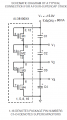
Can anybody give some idea why C1 and C2 capacitors bulge out (fails) for below circuit ?
The voltage across C1 and C2 are 2.5V in simulation but still do not understand why two upper capacitor C1 and C2 only fails.
Capacitor datasheet Link : https://www.mouser.in/datasheet/2/293/Electrolytic_Double_Layer_Capacitors_E-3082361.pdf