Why am I getting cut off?

Thread Starter

KCHARROIS

Joined Jun 29, 2012
312
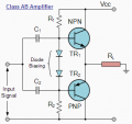
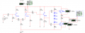
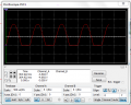
Hello everyone I have a circuit that works great until i get to my final stage which is a class AB and I seem to be getting cut off, images attached show this... Why am I getting cut off it doesnt make any sense everything seems to be in order?

Thanks
 

Attachments

Thread Starter

KCHARROIS

Joined Jun 29, 2012
312
Without the -25V at R13 and R14 my quiesent value was at half of my positive supply rail and my peak to peak voltage was under 10 V shouldnt it have worked anyways?
 

#12

Joined Nov 30, 2010
18,224
Theoretically, your first setup should work within the limitations of only having a drive voltage from zero to +25 volts, or, an output limitation of about +/-10 volts. I have to guess the simulator has a problem. There is no DC coupling to the output stage and it is self centering but the simulator doesn't seem to "get" that.

Try disconnecting the drive transistor and simulate a signal generator at the left side of the capacitors and see what the simulator does.

You need to be able to tell when the computer program is lying to you.
 

#12

Joined Nov 30, 2010
18,224
I don't Sim.

The first circuit I tried on a simulator was a jfet preamp with an opamp driving a constant current sink, and the simulator couldn't do it. No output. Does not compute.

WTF good is a simulator that can't do a single stage audio amplifier?

Oops, spelled "what" incorrectly.
 
Last edited:

#12

Joined Nov 30, 2010
18,224
The self centering, single stage, jfet preamp is one of my best achievements. It's the only circuit I've ever seen that could accept any jfet with 5 to 15 milliamps of idle current (2n4416) and center the ouput exactly between the rails while you plug in any replacement jfet with that part number. The goal is to have a high impedance preamp, on the end of a long cord, and not have to sort jfets or adjust anything when you change the cord with amplifier attached to the far end of it.
 

atferrari

Joined Jan 6, 2004
5,011
Check what is the output at the emitter of Q4. That should tell you what is going on.

Probably much faster than posting here.

Please tell what you found out.
 

#12

Joined Nov 30, 2010
18,224
Wow, you must have a time lag in Argentina! The problem is fixed and we had time to make derisive remarks about the simulator program that failed to give the correct answers.
 

Audioguru

Joined Dec 20, 2007
11,248
I think audio amplifiers were capacitor-coupled like that about 55 years ago.
Then and ever since they became DC-coupled with plenty of negative feedback.

The amplifier shown has NO negative feedback so its distortion must sound awful.
The differential input stage is perfect for negative feedback since its grounded and wasted input can be the negative feedback input.

Frequently in these forums Multisim doesn't know anything about electronics.
 

#12

Joined Nov 30, 2010
18,224
It also doesn't need 2 capacitors to couple the output stage to the driver, but he will address these things as his skill improves.
 

#12

Joined Nov 30, 2010
18,224
It's obviously student level, each stage being able to stand alone. The result that there is no feedback loop to clean up the distortion is a symptom of the original purpose...to teach amplifier stages, one at a time. It makes me think he's a student. At least he's doing his own work, which is better than a lot of students that come here!

I approve.
 

#12

Joined Nov 30, 2010
18,224
While we're hijacking this thread, can I ask please, does it really need 2 capacitors to couple the output stage?
 
Top