Why am I getting cut off?

Audioguru

Joined Dec 20, 2007
11,248
So I'm back...

The amp works somewhat the way I want it to. Sounds good but I dont like the fact that theres 2 Vdc going to my speaker should I be concerned?
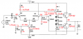
Your amplifier is amplifying its DC input offset voltage.
The output should be near 0VDC.

Connect a 0.47uF or 0.68uF poly capacitor in series with R13 to ground to block the amplification of DC.
 

Audioguru

Joined Dec 20, 2007
11,248
I think the current in the differential pair is too high and is higher than I calculated. That causes the current in Q1 also to be too high that causes the output offset voltage.
R11 severely reduces the AC and DC gain so the differential cannot cancel the offset.

1) Change the values of R5 and R6.
2) Remove R11.
3) Add a frequency compensation capacitor across the base and collector of Q1.

See my new schematic:
 

Attachments

Audioguru

Joined Dec 20, 2007
11,248
Ron, can you simulate it please? I don't have models for the darlingtons.

I think he has Q1 turned on too hard so the output voltage is too high and the R11 emitter resistor reduces the gain too much so it can't cancel the offset voltage.
 

Ron H

Joined Apr 14, 2005
7,063
Ron, can you simulate it please? I don't have models for the darlingtons.

I think he has Q1 turned on too hard so the output voltage is too high and the R11 emitter resistor reduces the gain too much so it can't cancel the offset voltage.
I did simulate it. The input offset voltage is only 5mV. This is with matched transistors in the differential pair, of course. This is why I think he has a wiring or component error.
Input bias current is high enough that the feedback resistor will affect output offset, but that is a minor issue.
 

Thread Starter

KCHARROIS

Joined Jun 29, 2012
311
Hi all,

Thanks for all the replies very well appreciated but I've revamped my amp to this new one, it will be louder without any DC voltage appearing at the speaker. Let me know what you think.

Thanks
 

Attachments

Audioguru

Joined Dec 20, 2007
11,248
I've revamped my amp to this new one....
Let me know what you think.
1) The differential transistors have very high current then the value of R6 is very low.
2) R1 can be replaced by a piece of wire.
3) Without a frequency compensation capacitor then the circuit will probably oscillate at a high frequency.

You are using weird resistor values: 9k, 500k, 8k and 4k.
 

Audioguru

Joined Dec 20, 2007
11,248
I have a huge problem with oscillation, how do I prevent it!
I mentioned adding a frequency compensation capacitor a few times to prevent high frequency oscillation. All opamps have one and most audio amps have one.

The capacitance of the transistors and stray capacitance in an amplifier causes phase shift at high frequencies. When negative feedback is added to control gain and reduce distortion then at a high frequency the negative feedback is phase shifted into positive feedback forming an oscillator.
The frequency compensation capacitor reduces the gain at high frequencies so the amplifier cannot oscillate.

Connect a 22pF, 47pF, 100pF or 220pF ceramic capacitor from the base to the collector of Q8 in your circuit. The higher values will cut the response at high audio frequencies and increase the distortion at high audio frequencies.

EDIT: Some amplifiers have a Zobel network (R and C in series) at the output to ground to form a load at high frequencies where the inductance of a speaker causes it to be a high impedance phase shifting load.
 
Top