Which USB adaptor/converter is this?

Thread Starter

dell101

Joined Jan 21, 2017
12
Hi Guys,

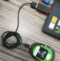
I am reviewing a GPS tracker from a Chinese company which is having some issue and need firmware debug. Their tech team wanted to debug the device and asked to connect the device using a "USB Connector" which they forgot to sent. Can you help me recognize this adaptor?

Device: GPS Tracker which has 4 pin connector.
Cable: USB cable with 4 pin magnetic pogo connector

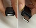
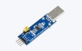
According to manufacturer if we connect the cable directly it will not recognize the device in Windows as COM port. Hence we need to connect the cable to this adaptor and then connect this adaptor to PC. This adaptor has female USB on one side and male usb on other. Drivers that they gave me is PL-2303.

Can you help me identify this adaptor/converter?

PS. It tried to google but I'm not sure which keyword to google. USB to USB is such generic term.

Thank You.
 

Attachments

meth

Joined May 21, 2016
298
If the driver is PL-2303, that that is USB-to-Serial. So the GPS communicates using Serial (RS232), and that little device converts it to USB. I guess the only trick is that on the device side the connector is also like USB, not the most common 9 pin D-SUB that is used in serial.
 

sagor

Joined Mar 10, 2019
1,046
PL-2303 is a Prolific device. Their drivers used to be known for conflicting with other USB drivers a few years ago.
Agree that the GPS is just a serial device and they made a serial to USB adapter in that small box. Why they used a USB connector for the serial connection is questionable, poor design.
Overall, I'd stay away from such a product myself. It seems like a hobby/back alley designed device with questionable (ie cheapest) interface chip (drivers). That is just my opinion, others may disagree...
 

Thread Starter

dell101

Joined Jan 21, 2017
12
Why they used a USB connector for the serial connection is questionable, poor design.
Probably because its a consumer cable used for charging and they wanted to interface with same cable.

Is it possible to make such interface by buying something off the shelf and connecting it to usb interface..

Thanks for your help.
 

sagor

Joined Mar 10, 2019
1,046
Probably because its a consumer cable used for charging and they wanted to interface with same cable.

Is it possible to make such interface by buying something off the shelf and connecting it to usb interface..

Thanks for your help.
It may have been cheaper to put the PL-2303 into the GPS device itself and then use a standard USB cable like they did, with nothing else required. Creating another external box to turn serial to USB just makes it more complicated, and probably costs more overall. Just like you started this post with, they "forgot" to send the adapter box to you. Now it costs them more to ship it to you. One part is easy to keep track of. Two parts makes it more complicated. Imagine users losing that box when they want to use the GPS device, they won't be able to...

Their box is not a "regular" off the shelf converter, seems to be custom made. There are many TTL (serial) to USB converter devices out there, but one has to figure out the wiring of the serial signals.
 

Jon Chandler

Joined Jun 12, 2008
1,560
It looks like they have improperly used a USB connector for UART serial instead of properly including a UART – USB converter chip inside the unit. So the "should-have-been-included" dongle is more-than-likely a UART – USB converter.

You could get a USB dongle like this one and build your own adapter.

To do so, cut the USB-A end off of a mating connector, and strip the 4 wires of the cable.

Two connections will be simple. The positive and ground wires will be as normal for a USB cable, and should be red or pinkish for +5v, black or gray for ground. Of the remaining wires, which may be green and white, one will be UART Tx and one will be UART Rx. Your guess is as good as anybodies.

If you have access to a volt meter, the Tx lines idle high (as I recall). Measure the voltage on each line to ground on the cut-off cable and on the USB converter. Connect the line with 3.3 or 5 volts from each side to the pin which does not have voltage on the other end.

After this, then you need to determine baud rate and other serial parameters. Not impossible but a bit of a hassle.

You might be better off to demand a refund. If the above is all Greek (or geek?) to you, that might be the best bet.


Screenshot_20250207_110236_Edge.jpg
 
Last edited:

Ya’akov

Joined Jan 27, 2019
10,226
Manufacturers have begin to omit the UART→USB* chips from devices in order to save on space and parts count. The ones I have seen have been with Type-C connectors (e.g. LilyGo) but the idea is the same whether is is C or micro… or mini.

In these USB port is present for power, not data, when the device is used by the ordinary consumer. If access to serial data is required—for programming, debugging, or updating—a device sits between the USB connector that is normally plugged in to power and the D+/D- pins are connected from the UART to the UART→USB chip (e.g.: PL2303).

This way you need only one of the converter chips, in the form of an external device, rather than putting one on every PCB. This is a savings to the manufacturer and has the advantage to the end user of avoiding the issues that have cropped up before such as when Prolific’s drivers bricked counterfeit Prolific chips.

If the latter happens—legitimately, or in error—it requires only replacing the external dongle and not the soldered-on chip, or more likely, the device it is soldered to.

Yes, if you can get the pinout of the device’s USB port it should be trivial to make your own converter. It could be in the form or a cable or something that sits between the cable and PC. It just requires one of the several BoBs (Breakout Boards) using the PL-2303 or one of the other chips commonly used for UART/TTL⁴ →USB conversion.

The purpose of the chip is to take the UART level serial signal and make it appear to the computer to be a USB serial device. It really should be very simple to accomplish.

Below is more than you ever wanted to know about UARTs and friends. You can read it if you want, but you don’t have to know these things to make your device work. On the other hand, I always find that knowing more makes success more likely.

*A UART (Universal Asynchronous Receiver-Transmitter) is a chip that allows for serial data communications between devices. Sometimes those devices are on the same PCB, or another contained in the same case. It was developed to make fast (at the time), flexible exchanges of data easy.

The UART is related, but not identical to, RS-232¹. UART is hardware and RS-232 is a standard that uses UART². A major difference between the plain UART and RS-232 is the voltage and polarity of the signals indicating logical high and low. The UART uses the PCBs logic level signals while RS-232(C) inverts the sense of things using a negative voltage for high and a positive voltage for low. UART will use 0V for low and \(\mathsf{V_{CC}}\)³ for high.

The table below compares and contrasts the two.

FeatureUARTRS-232C
DefinitionA hardware module/protocol that handles asynchronous serial communication.A standard defining voltage levels, signal timing, and connectors for serial communication.
Voltage LevelsLogic-level signals (e.g., 0V for low, 3.3V or 5V for high).±3V to ±15V (often ±12V for compatibility).
Signal TypeTTL (Transistor-Transistor Logic) level signals.Higher voltage signaling, requiring level shifting for MCU compatibility.
WiringTypically uses two wires (TX, RX) plus ground.Can include multiple control lines (e.g., RTS, CTS, DTR, DSR).
DistanceShort-range (a few meters at most) without special drivers.Longer-range (up to 15m at standard data rates, further at lower speeds).
InterfaceUsed inside devices or with direct microcontroller-to-microcontroller communication.Used for external device connections (e.g.: computers to peripherals).
UsageCommon in embedded systems, microcontrollers, and modules (GPS, Bluetooth, &c.).Found in legacy computer interfaces (COM ports), industrial equipment, and older systems.
Connector TypeNo standard connector, but it is very common to find .1”/.254mm pin headers used on PCBs, or for smaller devices, higher pitch headers or pogo pin contacts.DB9, DB25 connectors commonly used.


1. The “RS” in RS-232 stands for Recommended Standard. RS-232 was promulgated but the EIA (Electronics Industry Association) in 1960 and has been revised many times. The most commonly adopted version, EIA/TIA RS-232C, introduced in 1969 when the EIA merged into the TIA (Telecommunications Industry Association).

RS-232 (1960) had a voltage range of -5V to -25V for logical high and +5V to +25V for logical low while RS-232C has a range of -3 to -15V for low and +3 to +15V for high.

2. Almost but not quite always uses UART but RS-232 can be emulated in software and not actually use the UART.

3. \(\mathsf{V_{CC}}\) stands for Voltage Collector to Collector and was coined in the days of BJT (Bipolar Junction Transistors) before ICs were used. It’s counterpart \(\mathsf{V_{EE}}\) (Voltage Emitter to Emitter) was the low side of the circuit. Typically, these would be whatever the positive and negative voltage rails were tough that wasn’t always the case.

In modern parlance, when used in the context of MCU based circuits, \(\mathsf{V_{CC}}\) refers to the positive supply rail value—so 5V, 3.3V, 1.8V, &c. \(\mathsf{V_{EE}}\) is generally not used and 0V or ground (the latter being a confused misnomer) are used instead.

4. TTL refers to Transistor-Transistor Logic which is the construction of simple logic gates (AND, NOT, OR, &c) using BJT transistors. This circuitry is now hidden inside the MCUs and CPUs, but like \(\mathsf{V_{CC}}\) it has taken on the meaning of a voltage level—in this case 5V or 3.3V.
 

Thread Starter

dell101

Joined Jan 21, 2017
12
Thanks for your knowledge guys. I understand it now.
Here is what I plan to do. I have ordered a device like this PL2303-USB-UART-Board-type-A-V2. I will connect the USB female connector to it and it should hopefully work.

One thing I noticed is that their config app (windows) and their USB converter doesn't specify the BAUD rate. Is it something standard and doesn't need to be tampered with?

Thanks a lot.
 

Attachments

MrChips

Joined Oct 2, 2009
34,628
Go to the Device Manager and open the COM port assigned to the USB converter. You can set the baud there.
The app will also select the baud of the converter automatically. It still has to match up with the baud on your GPS device.
 

meth

Joined May 21, 2016
298
Try to find a manual of the GPS tracker.. there MIGHT be communication parameters. Probably not. Then it is trial and error.
 

MrAl

Joined Jun 17, 2014
13,667
Yeah that does look a little strange. USB does not do RS232 natively.

If you check in Device Manager you may find out exactly what it is. Then again, you may not because MS has strange ways of doing things all the time. For some devices it may just say "Generic Thing" :)
 
Top