Facebook
 Google
 GitHub
 Linkedin
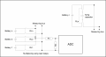
My project is to measure 12 V voltage of a number of batteries on the same circuit and then monitor on PC.
I'm not going to design one circuit for one battery but one circuit all batteries (36 batteries expected).
This circuit must be optimized to reduce number of electronic components. I, at the beginning, intended using some MUX to multiplex 12v signal from batteries before sending to MCU. However there is no MUX with 12 v (exactly 0 V-16 V) input.
I'm finding another component to replace MUX, does anybody help me?