Where to start - DSP filtering of a sine wave

Thread Starter

nanok66

Joined Jul 14, 2016
75
Hi all,

I have been working on personal project that involves counting the frequency of a sine wave around 4000Hz. My problems begin with the fact that the original sine wave I am detecting is very small (500nV pp). I am currently using a combination of an in-amp followed by an op-amp to amplify the signal with a total gain of around 1 million. As you might guess the sine wave is pretty noisy! I have experimented around with capacitor-resistor filters and I can certainly clean the signal up quite a bit, enough to clearly see it with my scope.

Yet still I am still unable to count the frequency with my PIC microcontroller. I tried using the Zero Cross Detection module and failed. I also tried creating a schmitt trigger circuit to convert the sine to a square wave and also failed. In both cases I believe I failed because the sine wave was not clean enough yet.

I recently got some advise to use DSP to clean up the signal. DSP would certainly cost more but I believe this is good advise. The only issue is that I have no idea where to start with DSP. I am already using a PIC microcontroller so perhaps there may be models that include some DSP functions but I am also interested in learning how to use a dedicated DSP chip alongside my PIC microcontroller if necessary.

If a DSP chip can clean up my sine wave I am totally confident I can use my PIC's functions (such as the Zero Cross Module) to detect the actual frequency, so I am specifically looking for advise on how to filter my sine wave with DSP. Any advise is greatly appreciated!!
 

Sensacell

Joined Jun 19, 2012
3,787
Do you have a phase reference for this signal?

A lock-in amp can do the job, but you need a reference signal.

EDIT- Duh, If you had a phase reference, you would not be taking about zero-crossing detectors.

What is it you are trying to do exactly?
 
Last edited:

danadak

Joined Mar 10, 2018
4,057
Some additional info -

For me what stands out is (below is PSOC 5LP family, 4 family a reduced set) -

1) Routability
2) Fast 12 bit SAR A/D and slow 20 bit DelSig
3) DFB (Digital Filter Block) that is dual channel, handle FIR or IIR filters, or DFB
can be used as a GP fast processor block, similar to RISC block
4) MSI logic elements GUI based and/or the UDB Verilog capability. Eg. the FPGA
like capability
5) Onboard Vref
6) IDAC, VDAC, OpAmps (up to 4), comparator, mixer, switch cap, analog mux....
7) LCD, COM, UART, I2C, I2S, One Wire, SPI, Parallel, LIN, CAN, BLE, USB
9) Custom components capability, create with schematic capture or Verilog
10) DMA to offload processes like filters, COM, Display
11) ARM M0 (PSOC 4) or M3 (PSOC 5LP) or 8051 core(PSOC 3) or M0+/M4 dual core PSOC 6
12) Extensive clock generation capabilities
13) All components supported by extensive prewritten APIs. So0 largely you call these APIs and do simple coding to effect system. C libraries.

https://www.element14.com/community/thread/23736/l/100-projects-in-100-days?displayFullThread=true

http://www.cypress.com/documentation/code-examples/psoc-345-code-examples

Great video library http://www.cypress.com/video-library

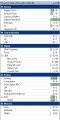
Attached component list. A component is an on chip HW resource. (PSOC 5LP family, 4 family a reduced set)

Free GUI design tool with schematic capture, "Creator". Components have rich API library attached to each component. Compilers free as well.

PSOC 4 is low end of family, consider 5LP parts as well. PSOC 4 also has arduino footprint boards (pioneer) as well. PSOC 6 dual core M0+/M4.

https://www.elektormagazine.com/labs/robot-build-with-cypress-psoc

http://www.cypress.com/products/32-bit-arm-cortex-m-psoc


https://brightcove.hs.llnwd.net/e1/...mp4?pubId=1362235890001&videoId=2606504288001

Regards, Dana.
 

Attachments

Last edited:

Thread Starter

nanok66

Joined Jul 14, 2016
75
Thanks Dana I appreciate the suggestion. Already a little over my head but I'll definitely read more about the chip you are recommending.

Sensacell I am striking a tuning fork of unknown frequency and picking up the resulting vibration with an EMAT (inductor coil). EMAT coils are not very efficient so the signal that is picked up is very small, hence the need for great amplification before I can count the frequency of the resulting sine wave. The sine wave picked up by the coil is also influenced by sound and general mechanical vibration of the whole apparatus. So i need to clean it up as best I can before i am able to discern the frequency.
 

danadak

Joined Mar 10, 2018
4,057
Consider using an accelerometer attached to the fork. Might
result in greater signal, you would have to do the analysis.

Also use a cantilever beam to get mechanical gain for the accelerometer.
Just a thought.

Regards, Dana.
 

Tesla23

Joined May 10, 2009
560
Hi all,

I have been working on personal project that involves counting the frequency of a sine wave around 4000Hz. My problems begin with the fact that the original sine wave I am detecting is very small (500nV pp). I am currently using a combination of an in-amp followed by an op-amp to amplify the signal with a total gain of around 1 million. As you might guess the sine wave is pretty noisy! I have experimented around with capacitor-resistor filters and I can certainly clean the signal up quite a bit, enough to clearly see it with my scope.
If you can clearly see the sine wave on a scope then you should have enough S/N to use one of the simple frequency estimation algorithms, google 'frequency estimation' or similar, I found this paper that might get you started:
http://staff.itee.uq.edu.au/vaughan/Publications/isspa-92.pdf
 

crutschow

Joined Mar 14, 2008
38,689
I have experimented around with capacitor-resistor filters and I can certainly clean the signal up quite a bit, enough to clearly see it with my scope.
Before going to the complexity of a DSP filter, I would suggest a high-order 4kHz band-pass active filter.
That will likely clean up the signal a lot better then passive RC filters.
How much deviation from 4kHz do you expect?
 

danadak

Joined Mar 10, 2018
4,057
Thanks Dana I appreciate the suggestion. Already a little over my head.....
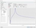
Keep in mind the DSP has a config wizard, you essentially pick topology,
set sample rate, type, order, FIR or IIR, and you are done.

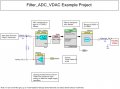
The DMA in the shown example (example code already done for you) can be a little
more challenging depending on A/D resolution you use and data alignment in byte/word
representation from your choice. But extensive example code and ap notes take care of
this. And of course going digital constrains substantially what would be errors for passive
component drift.

Regards, Dana.
 

Thread Starter

nanok66

Joined Jul 14, 2016
75
Tesla23, the article you linked seems to be super relevant to my problem. But whew that article gets technical! I assume I am supposed to adapt those formulas into my code for sensing my sine wave frequency? Again this is definitely over my head on how to implement but in general I don't understand how methods like this become useful if my sine wave is still noisy. I mean if I am using my PIC to detect a zero crossing for example, and the sine is so noisy it causes "false" zero crossings events to occur, how can I ever calculate the correct frequency if I am taking in false information?

Crutzchow, the range would probably not be more than 5% ie 3900Hz - 4100Hz.

And yes, the majority of the 100+ hours I have spent toying with this circuit have been messing with different filters. I am just a hobbyist though, nowhere near an expert on the subject.

One thing about filters that has eluded me is that the circuit diagrams for active high pass filters are essentially a passive high pass filter at the input of an op-amp. And for some reason I am unable to find a configuration of HPF (RC filter) that can be placed either before the in-amp OR between the in-amp and the op-amp. I can only see a sine wave in my scope if I have the HPF at the end of the chain (in-amp > op-amp > HPF). I have had fine success putting a LPF between the in-amp and op-amp. No idea why.
 

Sensacell

Joined Jun 19, 2012
3,787
A general rule that applies to DSP and everything else: garbage in, garbage out.

What you are trying to do accomplish seems very do-able if you go back to first principles and sort out a way to get a clean strong signal from the fork.
IMHO, All this DSP stuff will likely just derail your energy from actually reaching the project goal.

For example, you can also detect the vibrations optically, by passing a beam of light past the tip of the fork.
 

BobTPH

Joined Jun 5, 2013
11,618
I mean if I am using my PIC to detect a zero crossing for example, and the sine is so noisy it causes "false" zero crossings events to occur, how can I ever calculate the correct frequency if I am taking in false information?
If the frequency is always close to 4KHz, how about this?

Detect a zero crossing.
Disable detection for 1/4 of a cycle (the sin wave will then be near max or min).
Detect the next zero crossing.

This way you will get 2 zero crossing per cycle, ignoring any false ones.

Bob
 

Tesla23

Joined May 10, 2009
560
Hi all,

I have been working on personal project that involves counting the frequency of a sine wave around 4000Hz. My problems begin with the fact that the original sine wave I am detecting is very small (500nV pp). I am currently using a combination of an in-amp followed by an op-amp to amplify the signal with a total gain of around 1 million. As you might guess the sine wave is pretty noisy! I have experimented around with capacitor-resistor filters and I can certainly clean the signal up quite a bit, enough to clearly see it with my scope.

Yet still I am still unable to count the frequency with my PIC microcontroller. I tried using the Zero Cross Detection module and failed. I also tried creating a schmitt trigger circuit to convert the sine to a square wave and also failed. In both cases I believe I failed because the sine wave was not clean enough yet.

I recently got some advise to use DSP to clean up the signal. DSP would certainly cost more but I believe this is good advise. The only issue is that I have no idea where to start with DSP. I am already using a PIC microcontroller so perhaps there may be models that include some DSP functions but I am also interested in learning how to use a dedicated DSP chip alongside my PIC microcontroller if necessary.

If a DSP chip can clean up my sine wave I am totally confident I can use my PIC's functions (such as the Zero Cross Module) to detect the actual frequency, so I am specifically looking for advise on how to filter my sine wave with DSP. Any advise is greatly appreciated!!
I took your query at face value - you were looking at using DSP to estimate frequency, in that case it would probably be simpler, more accurate and more efficient to use a frequency estimator algorithm than filter and pulse count. You have not stated your problem, so I have no idea if this is appropriate.

If feeding a sine wave into a counter would provide adequate performance for your project, then we should investigate the analogue part of the system to see if this can be made to work well, before we wander into more elaborate solutions.

1. I assume that the 500nV p-p signal source is low impedance, so what is the equivalent input noise voltage of your preamp? You should be able to get down to around 1nV/√Hz.
2. You seem to be struggling with the bandwidth of the system. Design a 4kHz bandpass filter with 200Hz bandwidth to cover the 3900-4100Hz signal range.
3. With a 200Hz bandwidth, lets assume the noise bandwidth is 300Hz, so with 1nV/√Hz that will gives you an RMS noise level around 17nV. That's about a 20dB S/N, I would suspect you could pass that straight into a counter, possibly using a schmitt trigger if you have problems with spurious crossings.
4. Your signal amplitude is the voltage from the transducer, whereas the noise is dominated by the noise of the amplifier. As the impedance is likely low, you could look at using an audio transformer to increase the signal amplitude with minimal increase in noise. A microphone transformer may be worth a try, or, depending on the impedance of the source, some other audio transformer.

Good Luck.
 

crutschow

Joined Mar 14, 2008
38,689
One thing about filters that has eluded me is that the circuit diagrams for active high pass filters are essentially a passive high pass filter at the input of an op-amp.
Then you haven't look in the right places. ;)
What you describe is just a passive filter with an op amp buffer, not a true active filter.

Active filter means the op amp is actively involved in the filtering process with some positive feedback to get a proper multiple pole rolloff, similar to that from an LC filter.

I would start with a 3-pole high-pass filter with a 3.5kHz corner followed by a 3-pole low-pass filter with a 4.5KHz corner.
These filters are normally put near the end of the signal chain to remove all noise, including any from the amplifiers, unless you have a problem with the amplifiers clipping because of the noise.
 

Thread Starter

nanok66

Joined Jul 14, 2016
75
Sensacell, cool I would like to stick to analog if I can. I will continue experimenting with active filters.

BobTPH, that is a very original idea thank you I will certainly consider that moving forward!

Tesla, yeah I am using the AD8429 in-amp which does have around 1nV/Hz noise. The issue with the Schmitt trigger was the output looked like a dotted line square wave (many spurious signals) even though I paid close attention to the threshold levels, and tried many different threshold levels with no luck. Also thanks for the filter recommendation and yes I have considered audio transformers I just haven't given in yet because I know it will be a higher cost.

Crutzchow thanks for the specific filter recommendation - I will give it a shot. I am mostly learning everything by google searches through various websites. I am ready to take my learning to a higher level tho - do you recommend any particular website, book, or textbook for active filters? It's sometimes hard to filter out the crap on the internet from the good stuff.
 

crutschow

Joined Mar 14, 2008
38,689
do you recommend any particular website, book, or textbook for active filters?
Besides the Wikipedia reference I noted in post #14, this paper from TI looks pretty good.
This may also be of interest.
And here's another of particular interest to me. It's updated from an old handbook (circa 1963-66) put out by Burr-Brown (old op amp manufacturer absorbed by TI ) which was my introduction to active filters (I go waaaay back :rolleyes:). Before reading that I hardly knew they existed.

I've noticed that some articles refer to 1st order RC filters with an op amp as "active filters" but I think that's an incorrect definition.
To be "active" means that the op amp should be a factor in shaping the filter response, not just act as a buffer to a simple RC 1st order filter.
 
Last edited:

danadak

Joined Mar 10, 2018
4,057
Just for future reference if you get around to using digital techniques
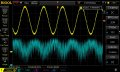
at a later time. This is result of prior PSOC digital filter post handling 4 Khz
buried in noise.

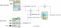
The sine was generated with PSOC wavedac component, the noise with its PRS module,
fed to a summer then to filter. All onchip.

There could be further optimization, a simple RC added to VDAC output to clean up
clock noise, diddling with the filter wizard for higher order filter.......

Garbage in, cleaned up waveform out.

See attached. Lots of fun working all onchip and GUI design tools. And
only 4 additional lines of code as this was an edited sample project. The
passives are offchip.

If you want project I will post it, and if you download Creator you can look
it over.

You can see it did not use much of the chips total resources, lots of other
functionality and tasks could have been added.......Also several of the resources,
WaveDAC, PRS, and OpAmp, can be dropped from design., they were just used
for test generation. That's another nice aspect of PSOC, generate your own test
bed for design debug.

Regards, Dana,
 

Attachments

Last edited:
Top