Where to solder DC jack?

Thread Starter

Sam11i

Joined May 11, 2020
12
Hi,

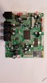
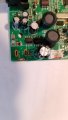
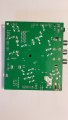
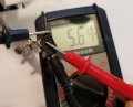
This board is from my son's cd player. The DC jack was torn off from wear and tear together with the pad to solder it back on. I did some google searches (without finding this forum) and saw about soldering it directly to the board, by scraping down to the copper base which I did. I think that just created a short.
With someone be able to guide me where / how to resolder the DC jack?


Thank you in advance!
Sam
 

Attachments

abrsvc

Joined Jun 16, 2018
138
This is a two sided board. The +5 on the back was soldered to the small pad only for support. It was not connected to the larger pad that you have scraped. Look for a connection on the top side of the board. Or just solder the ground connector on the bottom of board and leave the +5 clean. Be sure that the +5 is soldered to the pad on the top side of the board and that should "fix" the problem.

Dan
 

Thread Starter

Sam11i

Joined May 11, 2020
12
Hi Dan,

Thank you for the quick reply.
If I understood correctly I should solder points 1 and 2 on top and 3 on bottom in the attached photos.

1) Is there a method for soldering on top as the pads are covered by the jack when it's in place?
2) Do I need to cover the area I scraped on bottom? If yes, with what?

Thanks again,
Sam
 

Attachments

abrsvc

Joined Jun 16, 2018
138
It is hard to tell from the photos, but on the first one, solder the right hand connector and pad. For the one on the left, solder only the pin of the connector. There should be a "feed-thru" collar inside of the hole that should connect with the pin This is also physically connected (or should be) to the top pads. If you look carefully at the top of the board, there should be a separation between the oval pad and the surrounding metal on the one marked DC jack. The actual copper is under the green paint. Notice that the green is slightly darker there. With the +5, you see a lighter green which is the copper connection.
It is hard to see whether or not the feed-thru is still present for the +5 connection on the bottom of the board.

The bottom line here is that the two are separately connected. One on the top and one on the bottom. You may need to use wires to replace the feed-thru if it is missing.
 

Thread Starter

Sam11i

Joined May 11, 2020
12
Thank you Dan!

I did not understand everything you wrote in the second reply but I did get that the two sides of the board are separate and that I need to connect the jack to the top.

I soldered wires to the +/- on the top and then to the jack, reattached the jack repeatedly from the board with hot glue. All is working well.

My son is thrilled and I retained my super dad status ;-)

Thanks for your help,
Sam
 
Top