
Where to add a / some snubber network/s

Thread Starter

Dyslexicbloke

Joined Sep 4, 2010
566
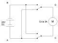
Hi folks I have the following circuit.
It is driving a set of guide vanes on a turbine but that inst impotent. The motor drives a high ratio reduction box so torque is fairly constant which may matter. Damage to relay contacts is an issue despite using contacts rated at 16A DC
upload_2018-7-26_17-2-49.png

Obviously I cant simply add a diode, as I would have done with a large solenoid.
I don't want o use a MOV as I understand the the failure mod id catastrophic and they degrade with repeated spikes.
Would a TVS and current limiting resistor help between nodes C-D

I am pretty sure an RC network between C-D would help but don't know how to optimise the values.

I also know that typically a switch would have an RC network across it however I have switches effectively between A-C / A-D / B-D / B-C
Can I / Should I add 4 networks? (One on each effective switch)
Would I leave C-D in place if I do?

Am I correct in assuming that damage is most likely as the switch opens, or bounces?
if so would networks B-C / B-D be effective, would C-D still be advisable.

Drowning in options and ignorance here, any and all comments welcome.

Thanks
Al
 

MaxHeadRoom

Joined Jul 18, 2013
30,708
If performing instant reversal especially with a motor operated G.B., there is very large current due to the reverse voltage opposing the generated voltage and also the very high current at the zero rpm point.
If not already fitted, some means of pause between reversal is needed.
Or a drive where the decel/accel can be controlled.
Max,
 

Thread Starter

Dyslexicbloke

Joined Sep 4, 2010
566
Never instantly reverses... PLC control
This is just the final output, such that it is...

Done this way to reduce coast as much as possible and remove the possibility of a code error or manual intervention shorting the supply.
That said, if it were a classic mechanically interlocked pare of two pole switches the question, from a node point of view would be the same.

Appreciate the heads up mind you... Pun intended
 

Thread Starter

Dyslexicbloke

Joined Sep 4, 2010
566
I have a similar problem on another site... Much bigger kit
48V DC, 80A start current and circa 14A running.
That motor is shunt wound and we only reverse the stator....

The answer to this question will also answer much of that... All be it at different values.
 

MaxHeadRoom

Joined Jul 18, 2013
30,708
One device that could be used is a relay with arc blow out contacts.
Or if any spare PLC outputs switch the BEMF diode in as needed with either direction and delay turn off.
Max.
 

Thread Starter

Dyslexicbloke

Joined Sep 4, 2010
566
Mmmm, switched diode, hadn't thought of that, Iike the lateral thinking....

However...

The big site, which was kicking bits of me, browning out the PLC and all sorts of nasty stuff has go a few bits from my emergency box lashed around it and although it isn't pretty or even as good as It could be it is working.

What I wanted to achiever was a design with some methodology behind it and although a switched diode would help it would not work in all situations. potentially causing a PLC IO upgrade on some sites.

These things switch regularly, typically once or twice a minute whilst the system is stabilising and perhaps a few time an hour after that.
Each time the river flow alters by more than a few % the system will have to compensate again.

Relay failure rate now is circa 1 / year / site, too much but not catastrophic.
Based on the box of bit experiment I am convonced RC is the way to go and pretty sure one design will cover a range of circumstances provided they are all 24V and in the same ballpark power wise.

I guess I am looking to be educated... I could test and measure this stuff but that would be very time consuming and involve halling a scope and a raft of bits to a site or building a rig in the workshop.
I am hoping to learn enough to get somewhere close ant then test a few variants for efficacy in the field.

Cheers
Al
 

panic mode

Joined Oct 10, 2011
5,071
more food for thought - what kind of motor are you using exactly. you mentioned " despite using contacts rated at 16A DC" but 16A is very low value for DC motors. what is the actual current that get switched? does motor stall or run with high load? example you mentioned peaks at 80A. is that the same unit?
 

Thread Starter

Dyslexicbloke

Joined Sep 4, 2010
566
OK Sorry... Forget the 80A stuff for now...

The relays are Finder ...
Single Pole 16A 24V DC Coil 38.01.7.024.0050

The motor in question has a current of around 5A, locked rotor, and is not loaded sufficiently to draw more than 3A, usually much less.
It is driving a huge reduction box that would break the driven shaft before stalling the motor.
We are counting input pulses and measuring the time between them with a PLC which gives us a good early indication that the load is increasing long before a current measurement, with anything basic, has a hope of giving us the same information.
However we also measure the current as a backup and to detect stall, just in case.

The motors vary slightly but are all series wound brushed units by Parvalux.
The motor drives a planetary gearbox, typically at a few tens of RPM at the output. (As supplied by Parvalux)
We mount these units on...
1. a second reduction box, the output of which turns a large shaft through about 70 Deg
2. a chain drive at circa 4:1 that turns a nut round a lead screw.

The former case always has fail safe limit detectors.
The latter case can have limits but usually we stall detect, using pulse time.
In both cases a pulse count is used to measure position

Should have been clearer, sorry
 

Thread Starter

Dyslexicbloke

Joined Sep 4, 2010
566
Thanks Max....
Need to absorb some of that before asking anything else, assuming I need anything else.

I take it a storage scope is the best testing method?
Anyone know just how much Voltage I will potentially be dealing with?
(Dont want to break my scope)
 

ebp

Joined Feb 8, 2018
2,332
If the schematic is correct then the relay contacts also short-circuit the motor in the STOP position(s). This adds an extra current-carrying closure for the contacts - probably always the same contact (e.g. the NC contacts if the relays are both dropped to stop the motor, which seems highly likely). It also means that that there is a discharge path for energy stored in the motor inductance. How soon the shorting occurs will depend on the method used to discharge the relay coil inductance, if it hasn't already all gone into an arc. If a diode across the coil is used, the opening will be delayed significantly and will be a bit slower once opening starts due to the low rate of coil current reduction, which is a bad thing in terms of arcing. You want the widest possible gap in the shortest possible time. The initial delay doesn't matter in that regard, but slower opening once it starts does. If a diode is used, It might be advantageous to change to a different circuit (RC or zener) that would allow faster drop-out.may have started and is then possibly sustained directly from the power supply. Changing the suppression across the relay coil could be advantageous even if motor shorting didn't occur.

When RC snubbers are used, their contribution to contact current at closure time must be considered. A snubber that does much good on opening of a contact will have a pretty low R, which could mean considerably more current on contact closure. A high value resistor across the cap can help by discharging it while the contact is open if sufficient open time is available and the steady-state current is tolerable.
 
Top





