When a filter is not what you think

Thread Starter

dcbingaman

Joined Jun 30, 2021
1,065
I was messing around with the following circuits in LTSpice and it got me thinking about how a student given such examples would do, being that the math states they should work fine but in practice no way!

1677444759052.png

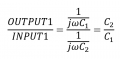
This looks, innocent enough, and the expected output would obviously be:

1677445188782.png
Thus it is frequency independent!

Another variation of this:

1677445061874.png

The transfer function becomes:

1677445538277.png

At high frequencies we get R2 over R1, at low frequencies we C8 over C3.

Of course they both have a serious issue that is not addressed by the math, as any current into the inverting input of the op amp will cause an imbalance of current and the op-amp will end up railing eventually or simply not staying centered around ground.

I saw this one from a student in a previous posting and it to will have issues especially if R6 is fairly high in resistance:

1677445861880.png

Attached is the LTSpice circuits for these.

I would like to find out how other people think about these kinds of circuits. I realize any 'imbalance' of current going into the virtual ground of the op-amps inverting input will result and a slow charging of the caps leading to problems.
 

Attachments

crutschow

Joined Mar 14, 2008
38,503
Students often get into trouble by assuming a real op amp is ideal so, when they start working with real ones, they need to learn their non-idealities, such as input bias currents and offset voltages, input common-mode voltage limits, gain-bandwidth, output slew-rate, and output voltage and current limits at a minimum.
if they ignore those, there's a good chance the circuit they design won't work with real parts.
 

Papabravo

Joined Feb 24, 2006
22,082
You are being less than mathematically rigorous in your algebra. In several cases you have indeterminate forms involving 1/0 and 0/0. These do not simplify the way you expect and they have little or no utility. I would think you should know better.
 

Thread Starter

dcbingaman

Joined Jun 30, 2021
1,065
Students often get into trouble by assuming a real op amp is ideal so, when they start working with real ones, they need to learn their non-idealities, such as input bias currents and offset voltages, input common-mode voltage limits, gain-bandwidth, output slew-rate, and output voltage and current limits at a minimum.
if they ignore those, there's a good chance the circuit they design won't work with real parts.
True. I think part of the problem is professors simply give out a problem say involving filter designs and always have the student assume an 'ideal' op-amp. This happens so frequently the students end up forming a nasty habit of always assuming that without looking at an actual datasheet.
 

Thread Starter

dcbingaman

Joined Jun 30, 2021
1,065
You are being less than mathematically rigorous in your algebra. In several cases you have indeterminate forms involving 1/0 and 0/0. These do not simplify the way you expect and they have little or no utility. I would think you should know better.
The only term that can possibly be zero here is the frequency in:

1677467782728.png

Being that a radian is unitless.

There is no value of time (in seconds) where the frequency can be 0 because it would violate the obvious.

Furthermore, AC analysis involves complex numbers for a good reason. It involves sinusoidal waveforms and or combinations of sinusoidal waveforms. By the very definition you cannot have a sinusoidal waveform that has an infinite 'period'.

DC analysis takes over. Of course in these circuits DC analysis brakes down and that is the whole point of the argument.
 

Papabravo

Joined Feb 24, 2006
22,082
The only term that can possibly be zero here is the frequency in:

View attachment 288479

Being that a radian is unitless.

There is no value of time (in seconds) where the frequency can be 0 because it would violate the obvious.

Furthermore, AC analysis involves complex numbers for a good reason. It involves sinusoidal waveforms and or combinations of sinusoidal waveforms. By the very definition you cannot have a sinusoidal waveform that has an infinite 'period'.

DC analysis takes over. Of course in these circuits DC analysis brakes down and that is the whole point of the argument.
If frequency cannot be 0, then tell me Herr Doktor, what is the frequency of a DC siginal?
 

MrChips

Joined Oct 2, 2009
34,807
The problem I see is having an opamp with no DC feedback from the output to the inverting input. Eventually, any and every opamp will drift and saturate to one of the supply rails.

In the third example, the voltage gain is -100.
But there is no DC reference on the input. Hence again, the output will easily saturate.
 

LvW

Joined Jun 13, 2013
2,026
In many cases, we assume an ideal behaviour of electronic components and parts.
This is even true for resistors and capacitors etc.
And it is a real challenge to know and to decide if for a specific application such an assumption is allowed or not.
Hence, in case of an opamp is necessary to know how it works and, in particular, which properties are "normally" idealized (gain function, input and output impedances, slew rate,...).
However, in any case (ideal opamp or not) one must know that resistive negative feedback is required for a usable DC operating point.
 

MisterBill2

Joined Jan 23, 2018
27,504
The reality of actual capacitors and inductors is often covered in the last half of the AC circuits analysis class. In the better classes it is covered in about the third class session, along with the caution that it will be ignored for a few weeks. And the better instructors provide cautions as to when they are using "Ideal" components.
 

BobTPH

Joined Jun 5, 2013
11,514
I don’t see that as a problem with non-ideal behavior, the problem is that there is an undefined voltage on the inverting input.
 
Top