What's wrong with this LTSpice Sim? -- NMOS and PMOS in SineWave

Thread Starter

Tonyr1084

Joined Sep 24, 2015
9,744
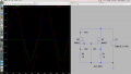
Learning to use Spice. I've drawn up this sim and for all intents and purposes it appears to be doing what it's supposed to do. Please understand this isn't anything I hope to build I just want to understand LTSpice better.

M1 & M2 are MOSFET's (N type and P type). I'm not certain I have them drawn properly, but from the scope it appears to do what I intended - to pass AC through a series of transistors. I've noticed that there is some clipping at the zero point (if that's the correct terminology) and am wondering why on that as well.

TP3 is the 2 volt sine wave. TP1 & TP2 are the voltages passing through the MOSFET's. What I'd like from you is to tell me what I created and if it's wired properly. Again, keep in mind I'm not trying to DO something, I'm just trying to learn something.

Thanks for all the help.
 

Attachments

Thread Starter

Tonyr1084

Joined Sep 24, 2015
9,744
When posting post #1 I failed to attach the file. I edited it and it is now posted. Sorry, I often do that - post something then have to edit it. Meanwhile people are answering the original question before I've managed to get the edit posted.
 

Thread Starter

Tonyr1084

Joined Sep 24, 2015
9,744
Didn't notice that. I moved things a little and failed to notice that. I'll edit it and repost it.

See what I mean? I'm mechanically inclined - there's nothing I can't screw up.

[edit] OK, trying again. Oh, and nothing changed on the waveforms.
 

Attachments

kubeek

Joined Sep 20, 2005
5,796
I think what you are looking at is the effect of the instrinsic diodes inside the mosfets. I don´t really know what you are trying to simulate, but possibly something simpler like a class-A single transistor amplifier might be a better start.
 

Thread Starter

Tonyr1084

Joined Sep 24, 2015
9,744
Kubeek: I'm just trying to learn more about LTSpice. The goal of the circuit is moot. It's the spawn of the notion that somewhere I heard that a MOSFET can pass current from D to S AND from S to D. According to LTSpice it doesn't appear to be so. And I'm not even sure if that's a definitive answer to that question either. It's just that I thought I read (or heard) that D & S are interchangeable. Is that true? If so - please help me understand.

Thanks.
 

Thread Starter

Tonyr1084

Joined Sep 24, 2015
9,744
Is the P Chanel wired correctly? Should the source be directly to ground? This is an AC circuit so would that matter? There's a lot to learn (for me) and I can use all the help I can get.

Way back in the 70's I learned BJT's, and at that I didn't even learn them very well. FET's are quite new to me - even though they've been around a long time. For a long time I was doing the family thing and didn't take time for my electronics hobby. Well, now I'm back to learning about this stuff - so - .
 

kubeek

Joined Sep 20, 2005
5,796
Yes mosfets can pass through current in both directions, but they still need the proper voltage between G and S to be open. N-channel needs roughly 5V on gate with respect to source, and P-channel needs -5V on gate with respect to source to be turned on.

What I was suggesting was that if you want to be more familiar with LTSpice, you probably should start with a circuit you are sure about and know exactly how it works and what to expect, then move onto circuits you don´t know.
 

Thread Starter

Tonyr1084

Joined Sep 24, 2015
9,744
Thanks Kubeek, that's pretty good advice. AND I've learned something about AC and MOSFETs. I'm going to modify this to supply a constant 5 VDC to the gate of the N chan and read (check for sine waves) coming through the FET.
 

Alec_t

Joined Sep 17, 2013
15,112
The inherent body diodes of the FETs don't show up in Spice and so catch a lot of people out.
This is effectively what your circuit looks like to Spice :-
BodyDiode.PNG
Another gotcha is that the generic FET models that you're using don't give realistic results. It's best to right-click the symbol and select a real-world FET.
 

Thread Starter

Tonyr1084

Joined Sep 24, 2015
9,744
Question about FETs: On an N-Chanel, to be "ON" the gate voltage needs to be lower (more toward zero OR more negative) than the source? Would the P-Channel be just the opposite? more positive than the source? Do I have at least that much right?
 

crutschow

Joined Mar 14, 2008
38,419
Below is the simulation of an N-MOSFET showing it conducting in both direction when on (Vgs=10V) for the first 4ms and conducting only in the reverse direction when off, due to the substrate diode (which is part of the simulation model here) after that.
You can see the reduced output voltage in the reverse direction due to the substrate diode forward drop of about 0.7V.

upload_2016-6-26_0-21-0.png
 

Thread Starter

Tonyr1084

Joined Sep 24, 2015
9,744
Obviously I have a lot to learn about MOSFETs and a lot to learn about using LTSpice.

I appreciate all your efforts in helping me to understand. The only way I'm going to learn is to keep messing with LTS and with MOS.

Thanks all.
 
Top