That explanation seems missing something. According to the article you shared, Vbb came to mean base to power supply not because Vb-Vb=0v, but because Vb-Vb=0v isn't a useful measurement. People decided, "Vb-Vb isn't a useful measurement, so let's decide Vbb will mean base-to-power." They knew it wasn't logical or consistent, they decided to give that notation a useful meaning (base-to-power), since it's logical meaning (0v) wasn't useful .
I think that by now everyone who deals with electricity well understands what those symbols mean. They represent" a DC supply of magnitude designed for desired operation of the circuit.
hi john,
If a drawing of a battery had to include a pair of plates for every 'voltage cell' it would not be practical.
You cannot infer the total voltage of a battery by the number of plates in a circuit diagram.
I use single pair and annotate the battery voltage alongside battery on the circuit drawing.
E
hi john,
If I drew a circuit that was powered by a single AA battery and used a single pair of plates to represent the battery, it would still be a battery.
Paraphrasing what Sigmund Freud said: if it looks like a cigar and it smells like a cigar, its a cigar.
How I draw a battery depends upon the symbols the drawing program has available.
eg: LTSpice uses 2 pairs of plates for all batteries another programs uses 2 or 3 pairs.
It doesn't really matter, I would suggest one pair is sufficient with text indicating the voltage alongside is understood by most readers.
I understand your desire for perfect symbols and communication, but you're going to have to relax just a little. There are a lot of things in this world that aren't standardized, and many more that weren't standardized until they had been around for a long, long time.
No matter what you, or anyone else, thinks these symbols should mean, they are actually used in different ways, with different subtleties of meaning, constantly. If you wed yourself to the idea that they mean one single, specific, perfectly accurate thing, all you're going to do is confuse yourself when you come across the myriad exceptions to your chosen interpretation.
Both symbols represent some kind of voltage source. I think that's universally accepted.
Both symbols represent a chemical cell or combination of cells. We probably all agree on that, but you'll find schematics and simulations where these symbols are used to represent other voltages, like signal inputs, or the voltage from a solar cell, etc. So already there are exceptions.
Trying to glean any more than that from the symbol is madness. Perhaps the symbols should have had useful, distinct meanings, but in practice you can't count on it.
If you want to find the best and/or most common meaning so that you can standardize use in your own schematics, that's great. Good for you. But don't expect the rest of the world to fall in line.
@johnyradio: Excellent trolling...
In such cases you should not ask people, but look in your country standard.
For example, Russian standard GOST 2.768-90 show that number of cells in circuit diagram may not be equal number of cells of real battery.
Below in picture from standard we can see 48V battery, plotted as one cell:
Just curious-- have you read all the posts in thread? I understand these particular symbols mean different things to different people. That's fine. I'm finding the general areas of agreement, and filtering out the illogical ones.Glad to bring your definition into the mix!
There are a lot of things in this world that aren't standardized
Seems to me, most schematic symbols are nonambiguous, and have clear, universally accepted meanings. Seems these particular symbols are atypical in that way. I'm cool with that.
The initial purpose of this thread, and still my goal, was actually not to find out the "standard" meaning, nor to collate a list of all possible meanings, but rather to find out what they mean in the schematic in the OP.
If you're saying the two symbols are equivalent in the schematic in the OP, I disagree. The author would not have done that.
Perhaps the symbols should have had useful, distinct meanings, but in practice you can't count on it.
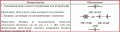
In the schematic in the OP, the symbol with 1 cell labeled "Vbe" represents a DC voltage source. Not necessarily chemical. In the circuit, it represents a generalized base-bias supply.
the symbol with multiple cells represents a higher DC voltage source. In this schematic, it represents the supply for the collector and its load resistor.
In other schematics, not shown here, the above meanings may be represented with other symbols. Or the above symbols may have other meanings.
In the schematic in the OP, the symbol with 1 cell labeled "Vbe" represents a DC voltage source. Not necessarily chemical. In the circuit, it represents a generalized base-bias supply.
the symbol with multiple cells represents a higher DC voltage source. In this schematic, it represents the supply for the collector and its load resistor.
In other schematics, not shown here, the above meanings may be represented with other symbols. Or the above symbols may have other meanings.
Admittedly, that would be an especially silly use in my opinion. I don't think I've seen it from any reputable designer, but I've certainly seen simulation files (LTspice, etc) uploaded to forums like this one with a battery symbol where they should've used an arbitrary voltage source. The sim works the same either way, but the schematic is less readable.
I certainly wasn't endorsing that usage, just using it as an example of how flexibly some symbols are used, and pointing out that you must be ready to use context to interpret them. Sounds like you've got the idea, so I won't belabor the point any further.
The two symbols in the OP are generally understood to represent DC sources, where the one with multiple cells has a higher voltage than the one with one cell, when both appear in the same schematic.
They may indicate 1-cell vs multicell.
They dont indicate (without additional notation) precisely how many cells, or precisely what voltages.
They don't indicate technology of source, chemical or otherwise.
They don't represent signal inputs.
Symbols which are understood only by their author, are irrelevant and off topic, as the purpose of shared schematics is to communicate something understood by others.
hi john,
If a drawing of a battery had to include a pair of plates for every 'voltage cell' it would not be practical.
You cannot infer the total voltage of a battery by the number of plates in a circuit diagram.
I use single pair and annotate the battery voltage alongside battery on the circuit drawing.
E
Yeah, imagine years ago when 45 and 90 volt "B" batteries were shown in circuit designs. Making 30 or 60 individual cells up would have made for some long batteries.

 Facebook
 Google
 GitHub
 Linkedin