What would be the reading before the xformer from this schematic ?

Thread Starter

Hextejas

Joined Sep 29, 2017
187
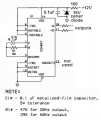
I am trying to build this beast but i dont have a transformer. So imagine if you will that tge circuit works and there will be some kind of current and voltage at the drain of the transistors. Is it a pulsating DC, AC, or other and how do I measure it ?
Simple-12-220-AC-to-DC-Inverter-Circuit-MOSFET-IRFZ44.jpg
 

MrChips

Joined Oct 2, 2009
30,806
The output at pin-11 and pin-10 are square waves in anti-phase, 0 to 12V.
That is when one output is 0V the other is 12V.

If you want to test the circuit without the transformer, connect 100-1kΩ resistors from the drain to +12V.
 

Thread Starter

Hextejas

Joined Sep 29, 2017
187
The output at pin-11 and pin-10 are square waves in anti-phase, 0 to 12V.
That is when one output is 0V the other is 12V.

If you want to test the circuit without the transformer, connect 100-1kΩ resistors from the drain to +12V.
As it exists now, the 2 drain wires are separated. Are you saying to connect them together and then 100, 1k resistors to the +12v ?
Could I use 1, 100k instead ? Or 2, 50k ?
Thanks
 

ebeowulf17

Joined Aug 12, 2014
3,307
As it exists now, the 2 drain wires are separated. Are you saying to connect them together and then 100, 1k resistors to the +12v ?
Could I use 1, 100k instead ? Or 2, 50k ?
Thanks
I read it that way at first too, but I believe the suggestion was for two resistors, and each one could be anywhere from 100 ohms to 1k.

Connect each drain to its own resistor, and the other side of each of those resistors connects to 12V supply.
 

MrChips

Joined Oct 2, 2009
30,806
As it exists now, the 2 drain wires are separated. Are you saying to connect them together and then 100, 1k resistors to the +12v ?
Could I use 1, 100k instead ? Or 2, 50k ?
Thanks
No. Keep the drain pins separate.

The resistance value is not critical. This is just for testing. Any resistance greater than 100Ω and less than 1MΩ would be suitable.

If you have two 100kΩ resistors or lower, connect one resistor between one transistor's drain and +12V. Connect the other resistor between the other transistor's drain and +12V.

What do you hope to see? You will need an oscilloscope in order to test that this is working.
 

DickCappels

Joined Aug 21, 2008
10,175
Note that the center tap is at 12V so you would square waves that switch between about 0V and about 24V plus there would be a certain amount of ringing and over/undershoot.

(Not directly related to your question, but in case you want to build There is no dead time and the output of a CD4047 is relatively slow, so you might see a lot of overlap in the conduction of the two MOSFETs, and that might mean excessive heating.)
 

Thread Starter

Hextejas

Joined Sep 29, 2017
187
The output at pin-11 and pin-10 are square waves in anti-phase, 0 to 12V.
That is when one output is 0V the other is 12V.

If you want to test the circuit without the transformer, connect 100-1kΩ resistors from the drain to +12V.
I am still playing with this and stuck. For some reason I can't get a voltage reading off of pin 11. Pin 10 reads 12v but pin 11 reads 0...
Is there something that I am doing that would prevent 11 from broadcasting ?
For pigs 1-3, I have tried 2 different RC combos.1st was 100uf and 20ohms. I calculated, perhaps incorrectly, that it gave me close to 60Hz which is what I want.
Now I have a 17k, 220nf combo. Same results.
Such a puzzlement.
 

ebeowulf17

Joined Aug 12, 2014
3,307
This may be a dumb question, and may have nothing to do with your current problem, but why would you put 220ohms between your supply voltage and the 4047 VDD pin?

Also, do you have any decoupling caps at the VDD pin? I don't see them listed in datasheet, but my understanding is that is always a good idea.
 

Audioguru

Joined Dec 20, 2007
11,248
For pigs 1-3, I have tried 2 different RC combos.1st was 100uf and 20ohms. I calculated, perhaps incorrectly, that it gave me close to 60Hz which is what I want.
I think you destroyed the CD4047 by using 20 ohms that is FAR less than the minimum of 10k ohms shown on the datasheet from Texas Instruments. They say the resistor should be between 10k and 1M. The almost dead short of 20 ohms and the fairly high supply of 12V cooked the transistor at pin 2 of the chip. For 60Hz outputs use 39k ohms and 100nF (0.1uF)metalized film, 5%.

Another problem is the missing spike prevention 16V zener diode and 100nF capacitor to ground at the left side of the 220 ohm resistor. Without these missing parts the transformer's inductance caused a high voltage spike that zapped the CD4047.

What do you have that works from the antique waveform of a squarewave? Almost anything electronic relies on the much higher peak voltage of a sinewave produced by your home's electricity. The squarewave inverter was used a long time ago for heaters and incandescent light bulbs where the average power from a squarewave and a sinewave were the same but their peak voltages were different.
 

Attachments

Thread Starter

Hextejas

Joined Sep 29, 2017
187
This may be a dumb question, and may have nothing to do with your current problem, but why would you put 220ohms between your supply voltage and the 4047 VDD pin?

Also, do you have any decoupling caps at the VDD pin? I don't see them listed in datasheet, but my understanding is that is always a good idea.
It's not my design, I borrowed it from probably a solar inverter project.
 

Thread Starter

Hextejas

Joined Sep 29, 2017
187
Thank you audio and its a good thing that I bought a few of 4047. This too is part of my learning experience.
I had a look at the data sheet for about 45 minutes before I found the restrictions that you mentioned. There sure is a lot of stuff in there. Tons of graphs.
The RC combo that fried the chip is my doing. I took a look at what electrolytic caps I had, (100uf), what freq I wanted (60Hz) and worked backwards.
Your phrase about a dead short resistor is another learning experience. I had never considered it. Now I will pay more attention to it.
Why use the 4047 ? Well it seemed to be popular when I googled a DIY, DC to AC inverter.
Again more learning. I wanted to wind up with a low voltage (<36), rough wave form, to see if I could clean it up.
I was hoping that the 4047 would give me that.
Please keep in mind that I am very new to this and am trying to keep the voltages and current low in case I get bit.
 

Thread Starter

Hextejas

Joined Sep 29, 2017
187
Another problem is the missing spike prevention 16V zener diode and 100nF capacitor to ground at the left side of the 220 ohm resistor. Without these missing parts the transformer's inductance caused a high voltage spike that zapped the CD4047.

What do you have that works from the antique waveform
Well, I am an antique so it fits

Thanks for your schematic, I will use it promptly.
George KG5TKY
 

dendad

Joined Feb 20, 2016
4,476
A good rule is to keep one hand in your pocket when poking around high volts. Then if you get a bite, it will not be across your heart.
Just be extra careful.


I'm a bit of an antique too!
VK3ZYZ ;)
 
Last edited:

MrChips

Joined Oct 2, 2009
30,806
No I don't but it's on my Christmas wishlist

I will be a bit handicapped until this thing gets here. Not even sure how well it will work.
http://www.piccircuit.com/shop/pic-...stick-pic18f2550-io-board.html?ps_full_site=1

I might have to do something before that.
I like to view waveforms on an oscilloscope to confirm things are working right. Personally, I would scrap any idea of a USB scope and would look around for a used analog scope under $50 if you are on a tight budget. A new digital scope can be had for under $300.
 

shortbus

Joined Sep 30, 2009
10,045

Audioguru

Joined Dec 20, 2007
11,248
The CD4047 makes a very nice perfectly symmetrical squarewave because it uses a digital frequency divider. An SG3525 can do the same or make a pseudo-sine/squarewave with PWM if you need it.
 
Top