What type of antenna is this?

Thread Starter

EnergeticEnvoy4486

Joined Oct 29, 2024
4
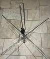
Please can someone help me understand what type of antenna is in the attached pictures, and what it's characteristics might be (as a receiver)? (I'm afraid I'm very new to the world of RF, but want to learn!)

The total height of the vertical part is 80 cm. The bottom part (containing the brackets for the horizontal parts) below the plastic connection box is about 35 cm. The top part, above the connection box, is about 40 cm. As you can hopefully see in the pictures, this top section doubles over to form a tall hoop and connects to the bottom part behind the connection box. Each of the 4 horizontal parts is about 75 cm long
 

Attachments

LowQCab

Joined Nov 6, 2012
5,101
Very unusual, a Vertical-Loop sitting on a Ground-Plane, I've never seen that before.

It looks like it might be for Local-Digital-TV.
The ultra-cheap construction would indicate that it was not
designed as a serious Commercial-stand-alone-Product,
but more likely a "give-away", or "starter", or "comes complete with a free" Antenna.

I would tend to think that it's not worth messing with.
If someone has a VNA-Analyser who knows how to use it,
it would be possible to document it's performance and find the Frequency-range it was designed for.

It's probably sorta-kinda "OK" for a very limited Frequency-range, which You may have no interest in.
.
.
.
 

MisterBill2

Joined Jan 23, 2018
27,501
It looks like a folded monopole with a ground plane. I would not classify it as a "loop" because of the narrow spacing. It appears that it would be omnidirectional, not a "beam" antenna.
I think that I see two terminals in the one view.
 

Thread Starter

EnergeticEnvoy4486

Joined Oct 29, 2024
4
Thank you both for your replies.

@LowQCab Yes, I expect this was an inexpensive entry-level antenna

@MisterBill2 Yes, that connection box has two terminals - one connected directly to the upper portion of the vertical, the other connected to the lower portion, so any current between the terminals has to pass through the hoop.

I keep seeing things like an antenna length being 1/2 wavelength or 1/4 wavelength. For something like this, where it's folded over and the co-ax connections are towards (but not at) the bottom, what counts as the antenna length? Is it the overall top-to-bottom height of the whole pole (i.e. 80 cm), the distance from the top to where the hoop joins back on (i.e. the height of the loop), the length of metal in the loop (i.e. the height doubled), or...?
(Or have I completely got the wrong end of a stick somewhere?! Sorry, I did say I was new to this...)
 

LowQCab

Joined Nov 6, 2012
5,101
There's no way, ( without documentation, and/or, a VNA Analyser ),
to know what exact Frequency it "should" work at because it's definitely an unusual design.
Who knows, maybe you'll get lucky.
.
.
.
 

nsaspook

Joined Aug 27, 2009
16,320
Thank you both for your replies.

@LowQCab Yes, I expect this was an inexpensive entry-level antenna

@MisterBill2 Yes, that connection box has two terminals - one connected directly to the upper portion of the vertical, the other connected to the lower portion, so any current between the terminals has to pass through the hoop.

I keep seeing things like an antenna length being 1/2 wavelength or 1/4 wavelength. For something like this, where it's folded over and the co-ax connections are towards (but not at) the bottom, what counts as the antenna length? Is it the overall top-to-bottom height of the whole pole (i.e. 80 cm), the distance from the top to where the hoop joins back on (i.e. the height of the loop), the length of metal in the loop (i.e. the height doubled), or...?
(Or have I completely got the wrong end of a stick somewhere?! Sorry, I did say I was new to this...)
https://educ.jmu.edu/~fawcetwd/archive/IEEE.pdf
MF AM Folded Monopole Characteristics

https://www.sciencedirect.com/topics/engineering/monopole-antenna

1730329492169.png


With the ground plane you then have the electrical antenna image.
https://en.wikipedia.org/wiki/Image_antenna

1730328202279.png
 

LowQCab

Joined Nov 6, 2012
5,101
Some good information there ........

But this makes me wonder about the Thread-Starters intentions.

Did You just happen to stumble upon this odd Antenna and it
gave You an inspiration about maybe it could be part of your next project ?,
or,
are You currently working on a project which You still need an Antenna for,
and thought maybe this one would work ?

What is it that You are looking for ?

High-Performance-Antennas are not terribly difficult to build,
but each design has it's pros and cons
and some designs can be quite finicky regarding precise dimensions,
plus odd things like "how many feet above the Ground it will be mounted",
or the trade-offs like, a bigger, higher, Antenna will have superior performance in theory,
but may lose that performance advantage because of the
additional loses in the required, much-longer, Coax-Cable run
between the equipment and the Antenna.

With Antennas, everything is a trade-off.
.
.
.
 

Thread Starter

EnergeticEnvoy4486

Joined Oct 29, 2024
4
Very interesting, thank you.

I’m about to get my first SDR and a friend mentioned they’d had this old antenna in the loft for years and would I like it. I’m only at the stage of beginning to explore the radio world so don’t have any expectations or requirements, just interested to learn and experiment
 

MisterBill2

Joined Jan 23, 2018
27,501
Actually, a common antenna SWR analyst device is able to show the resonant frequency with "close enough" accuracy for most receiving applications. I use an old MFJ249 to evaluate unknown antennas, and while the resolution is good the accuracy is just "OK", and for many applications that is close enough.
With the connection scheme appearing to be two screw type connectors, it is my guess that it is a receiving type of antenna, for signals in the lower end of the UHF Television broadcast spectrum.
 
Last edited:

nsaspook

Joined Aug 27, 2009
16,320
Actually, a common antenna SWR analyst device is able to show the resonant frequency with "close enough" accuracy for most receiving applications. I use an old MFJ249 to evaluate unknown antennas, and while the resolution is good the accuracy is just "OK", and for many applications that is close enough.
With the connection scheme appearing to be two screw type connectors, it is my guess that it is a receiving type of antenna, for signals in the lower end of the UHF Television broadcast spectrum.
I agree, the only thing weird for TV use is the vertical polarization. UHF Television broadcast is usually mainly in the horizontal plane. The difference between horizontally and vertically-polarized signals can be as great as 10 dB (Rabbit ears moving up/down for the best signal as the polarization changed with weak signals). With analog FM transmitting a more circular polarised signal, that means vertical or horizontal antennas have about the same 3db loss.
No idea what it was used for but a WAG would be for some sort of FM VHF/UHF analog voice service from decades ago.
 

LowQCab

Joined Nov 6, 2012
5,101
Look into an on-line Wavelength to Frequency Calculator,
then keep in mind that the lower the Frequency goes,
the longer/bigger, ( in physical dimensions ), the Antenna must be for best performance.

Also remember that "receive-only" Antennas are
not quite as fussy about having to be "tuned to resonance" at a specific Frequency,
like most transmitting-Antennas definitely are,
never the less, the very best receiving-performance will still be had
with a "tuned-directional-Antenna",
meaning that the Antenna will exhibit "Gain" in a particular Frequency-range, and in a particular direction.
.
.
.
 

MisterBill2

Joined Jan 23, 2018
27,501
Looking back at the dimensions given in post #1, I am guessing it would be for the "UHFHigh-band", in the range of 420 to 460 MHz. So it could be a scanner antenna or possibly even used for HAM radio communications, although the feed is not right, at least as I see it.
 
Top