As the title suggests I was wondering if someone could share some knowledge with me regarding the max output voltage swing of a BJT Common emitter inverting amplifier.
It's determined by the value of the power supply, whether there's an emitter resistor, and the bias point of the collector voltage. For example, the maximum would be if there were no emitter resistor and the collector was biased at 1/2 the supply voltage. For those conditions the maximum pk-pk output voltage would be close to the supply voltage.
Without doing all that math stuff, the basics go like this: The emitter voltage is somewhere above ground because you told it to be with the emitter resistor and the base biasing resistors. Whatever voltage that is left is used up by the collector resistor and the collector of the transistor.
So lets say you have the emitter 2 volts positive with an idle current of 1 ma and you're running on a 9 volt battery. There is apparently 7 volts you haven't used up, so you decide the collector resistor must use up half the 7 volts (3.5 volts). 3500 ohms, right? Not quite. As the transistor shuts off, the full 9 volts is available on that half of the wave, but as the transistor increases current and the collector resistor uses up more and more of the 7 "available" volts, you get to the point that there's nearly nothing left for the transistor so you can't actually get to 2 ma max. You can get pretty close, but distortion builds up in the last few tenths of a volt. That means you can't really use the whole 7 volts to make a sine wave. More like 6.7 volts peak to peak.
Now the math majors can do the details if that's what you want.
It's determined by the value of the power supply, whether there's an emitter resistor, and the bias point of the collector voltage. For example, the maximum would be if there were no emitter resistor and the collector was biased at 1/2 the supply voltage. For those conditions the maximum pk-pk output voltage would be close to the supply voltage.
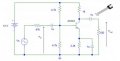
Please see attached the JPEG of the circuit I am looking at.
I can see that VB is equal to half Vcc since VB = 12(4.7/9.4) = 6V.
That VE = VB-0.7 = 5.3V
That VC = (VE/RE)*RC.
What is catching me is the visualization of how the BJT responds to the small signal voltage.
Since it has already biased and IE = IB + IC ....where IC is 99% of IE. Does the small signal see two paths when looking in from the base; RC||RL and through the emitter to ground?
As the base current increases the emitter current increases by Ib times the Beta (current gain). This increase in emitter current causes a corresponding increase in the collector current through the collector resistor. This causes the voltage drop across the collector resistor to increase, which reduces the voltage at the collector.
Thus an increase in the base current causes a reduction in the collector voltage.
Similarly a reduction in the base current causes an increase in the collector voltage.
 Facebook
 Google
 GitHub
 Linkedin