What kind of latch is this?

Thread Starter

El3

Joined Sep 13, 2014
37
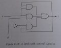
We're going to start to study about latches in my course. I have studied something on my own on the web and found something about different latches like SR-latches, JK-latches etc. But my course book is weird. They don't even bring up SR or JK but the first circuit for a latch they decide to bring up looks like this:


And they don't really explain how they come up with this circuit diagram in the first place and they don't explain it in the book (yeah, the book kind of sucks). I haven't seen this kind of latch anywhere or been able to find information about it. So I hope someone here can tell me, what kind of latch is this? And where kind I find proper information about it?
 

Attachments

absf

Joined Dec 29, 2010
1,968
It is a latch similar to TTL SN7475 or SN7474 without reset and clear inputs. The 7475 uses enable to enable the latch. Your latch uses a clock to enable it.

See datasheet pdf attached.

Allen
 

Attachments

crutschow

Joined Mar 14, 2008
38,819
It is a latch similar to TTL SN7475 or SN7474 without reset and clear inputs. The 7475 uses enable to enable the latch. Your latch uses a clock to enable it.
It may be similar to the SN7475 which is a latch that operates on clock levels, but the SN7474 is an edge-triggered flip-flop, which changes state only at the clock edge and ignores levels otherwise.
 

Thread Starter

El3

Joined Sep 13, 2014
37
Thanks for your replies. The subject of latches is new to me so I appreciate help in understanding it.

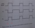
Here's another picture from the book next to the latch circuit:


For this kind of pictures, I wonder the following:
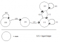
1. What do the vertical lines represent? (I marked the four first with red arrows) Why are the two first lines very close to each other, then a longer gap until the third?
2. What is it that makes the graphs look like they do? As I understand it, the clock signal is what initiates the others, that's why it's changes value on the first vertical line. But why does the first control signal change value already on the first and last (in a cycle) vertical lines, while the second control signal only changes value on the second and the third vertical lines?
 

Attachments

Last edited:

Thread Starter

El3

Joined Sep 13, 2014
37
Each line represents a respective point in time.
Yes, I already understood that much. I had many more questions though, I would prefer if they weren't completely ignored:

1. Why are the two first lines very close to each other, then a longer gap until the third?
(Yes so there's a longer time between them, but why then these particular intervals?)
2. What is it that makes the graphs look like they do? As I understand it, the clock signal is what initiates the others, that's why it's changes value on the first vertical line. But why does the first control signal change value already on the first and last (in a cycle) vertical lines, while the second control signal only changes value on the second and the third vertical lines?
 

MikeML

Joined Oct 2, 2009
5,444
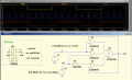
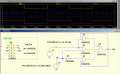
The relative time between the vertical lines is totally arbitrary. The data input V(x) in Alec's sim is asynchronous with respect to the clock V(ck). The data can change while clock is high or while clock is low.

The questions are how does the relative timing of the two inputs effect what happens at the output? Look up the meaning of "set-up time" and "hold time".

What happens to the output if data changes while the clock is high? Make a Truth Table of all of the possible combinations of output vs the inputs...

Some useful reading is at the section "Gated D Latch" here.
 
Last edited:

Alec_t

Joined Sep 17, 2013
15,156
I had many more questions though, I would prefer if they weren't completely ignored:
They weren't ignored; they simply weren't understood. What is the second control signal? How does it relate to the latch? We don't have your text book in front of us, nor a crystal ball ;).
 

MrChips

Joined Oct 2, 2009
35,183
All latches (flip/flops) rely on feedback from the output to the input.

For starters, study the behavior of this circuit:


After you have understood its operation I will post the next stage.
 

Thread Starter

El3

Joined Sep 13, 2014
37
All latches (flip/flops) rely on feedback from the output to the input.

For starters, study the behavior of this circuit:


After you have understood its operation I will post the next stage.
Sounds good. So here A is the input and Q is the output, and the output will depend not only on the input, but also on itself (it's previous state). So it all depends on

1. In which state we start (let's call this the "Starting state")
2. Which state we switch to from the starting state ("Second state").
3. What state we finally end up in ("End state")

So we get the following possibilities, for A/Q
Starting state | Second state | End state
0/0 | 0/0 | 0/0
0/0 | 1/0 | 1/1
0/1 | 0/1 | 0/1
0/1 | 1/1 | 1/1
1/1 | 0/1 | 1/1
1/1 | 1/1 | 1/1

State transition graph:


Some combinations are not possible, like for example we can't start in state 1/0 since that's an unstable state which automatically leads to 1/1. Also we can only change the input value in our state transitions, so we can not go from from any state -/- to -/-'.

This circuit seems to be only "2-step" (starting state and second state) dependent. I guess there can be longer chains than two steps also, if we have several latches/flip-flops in series.

So far so good?

So then I just wonder, is there some default state that we always always assume we start in or is that completely arbitrary? Do we always start in zero input and zero output for example? Or some other values?
 

Attachments

MrChips

Joined Oct 2, 2009
35,183
Not bad for a start.

The state diagram should show the state of Q alone, not A/Q.

The input condition A is shown in the lines with the arrow.


What does this state diagram tell us about the behaviour of this circuit?
 

Thread Starter

El3

Joined Sep 13, 2014
37
Not bad for a start.

The state diagram should show the state of Q alone, not A/Q.

The input condition A is shown in the lines with the arrow.


What does this state diagram tell us about the behaviour of this circuit?
It seems you found a simpler state diagram for the circuit.

Could you please answer my question, is there some default state that we always always assume we start in or is that completely arbitrary? Do we always start in zero input and zero output for example? Or some other values?
 

MrChips

Joined Oct 2, 2009
35,183
I did not find a simpler state diagram. It is the only state diagram.

There is no default state.

Study the simple circuit I presented. You will discover the "default" state.
 

WBahn

Joined Mar 31, 2012
33,198
To answer an earlier question you had, the vertical lines are just to visually tie related events together so that you can better see what causes what. In this case, I'm assuming that there is a circuit that takes a clock signal and generates two control signals from it. The rising edge of the clock causes an immediate change in the first control signal and a delayed change in the second, while the falling clock causes an immediate change in the second and a delayed change in the first.

Are you SURE that the timing diagram in Fig 6.20 is for the circuit in Fig 6.18? It doesn't appear to be since it has two control signals while the circuit only shows one. Also, the timing diagram has a clk signal and two control signals, while the circuit has no clock and just one control signal (or one clock and no other control signals). What is Fig 6.19?
 
Top