What is wrong with this flyback MOSFET voltage?

Thread Starter

jm233h12

Joined Jan 9, 2020
10
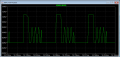
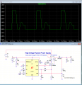
I have took an example 300V flyback circuit from Analog that converts 12VDC into 300VDC. I have a separate converter which I use to convert 270VDC to 3kVDC but I wanted to attempt it with a flyback to see what happens, so I have changed a few things around to try and attempt this. I get the correct output voltage and output current, but I get some strange waveforms on my MOSFET which are carried across to the output diode. It seems to be maybe be reflected voltage from the secondary side diode. Is this correct? How to eliminate it?

Are there any significant drawbacks to using flybacks in this type of application, with 600W output power? Any advice on how I can demonstrate these issues?
 

Attachments

kubeek

Joined Sep 20, 2005
5,796
What average power dissipation do you get in R9? That would be my biggest concern, and the second one would be obtaining a mosfet for such high voltage.
 

ronsimpson

Joined Oct 7, 2019
4,690
You are going to have a hard time finding diodes. That can be fixed.
Do you want continuous mode? It is harder on the diode and MOSFET.
Now you have 270V and 12V. I assume you want the 12V supply to go away.
What are you using the 3kV for? 600 Watt? So you will pull 2.3 amps from the 270V.
 

Thread Starter

jm233h12

Joined Jan 9, 2020
10
JM is trying to stop the "ringing" that is normal. I would not use the RC.
During the ring the energy in the transformer is down to almost zero. There is no energy there.
Okay, so I should remove the RC circuit network? The voltage I have shown is across the MOSFET. So if I remove the RC network that large voltage peak should be removed? Then I wouldn't need a MOSFET for that large a voltage peak.

Re: DCM v CCM, I think DCM? So that the secondary diode can be soft switched.

Power dissipation screenshot attached. I am unsure how to measure the average.
 

Attachments

Thread Starter

jm233h12

Joined Jan 9, 2020
10
By the way! I did not add the RC snubber circuit. It was included standard in the Analog circuit. I increased to suppress some ringing frequency I observed. Here is waveform with RC removed.
 

Attachments

Last edited:

ronsimpson

Joined Oct 7, 2019
4,690
It would be much batter if you attach your .ASC file.
I think your transformer turn ratio is not 1:10 as the text said. To get to 1:10 the secondary L=10m. This will pull down the MOSFET voltage!
 

kubeek

Joined Sep 20, 2005
5,796
Just a side note, mosfet models in ltspice don´t reflect the maximum Vds? I know diodes do, so I expected the mosfet to behave in a similar fashion, but this 30V one happily survives 1100V :D

And JM, that transformer is stil not 1:10, it is more like 1:3
 

Thread Starter

jm233h12

Joined Jan 9, 2020
10
Just a side note, mosfet models in ltspice don´t reflect the maximum Vds? I know diodes do, so I expected the mosfet to behave in a similar fashion, but this 30V one happily survives 1100V :D
I'm not actually sure. I am meaning to change the MOSFET used but I wasn't sure whether the waveform itself was correct as it looked strange to me. I know flybacks are typically used in HV applications, but why if the MOSFET suffers that large reflected voltage across it when the diode conducts in the secondary in DCM?
 

kubeek

Joined Sep 20, 2005
5,796
I'm not actually sure. I am meaning to change the MOSFET used but I wasn't sure whether the waveform itself was correct as it looked strange to me. I know flybacks are typically used in HV applications, but why if the MOSFET suffers that large reflected voltage across it when the diode conducts in the secondary in DCM?
I edited the post above as you posted this, the transformer is still not 1:10, you need the inductance to be 100u:10m.
 

kubeek

Joined Sep 20, 2005
5,796
You could go with even less than 1:10, but that increases the voltage stress on the transistor as you can see in the simulation. Higher ratio is worse in terms of transformer size and price.
Just to make sure, transformer ratio is not the same thing as inductance ratio.
 
Top