Lol I have a board that i had made well it was the first one I had made using EasyEDA
It didn't work worked great on bread board worked great on strip board that i soldered up.
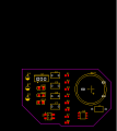
I looked at the 10 i had made put 2 together
got mad and threw them away They looked so nice I just no they had to work.
Well they don't 2 days later I took a look at the board the power was backward
my regulator was not getting power and my 3.3 volt pin was at 5 volts i missed this because
i did check the board after i auto router it. and it came back i had no errors the auto router
changed the power tracks.
Schematic was right but the TS don't seem to have any tracks on there board.
Looks like a wireless battery charger. Break the design into parts and measure voltages. For example, does the LED light? Is there voltage at R2? How about pin 2 of the bridge rectifier, and so forth.
I am not an EasyEDA user, but there are some symbols on the schematic that are worrisome. What do the black and red dots mean? With Eagle, dots (green) from a pin of a component to a wire can mean a connection with overlap. Are the wires in your schematic "nets" or just "lines?" That is, are you sure the EDA identified them as signals?
What does the circled dot mean:
How is R5 connected here:
That is, is it connected across C7 or is C7 connected across the battery and R7 is simply laid across that part of the schematic? Why doesn't C7 have black dots at its ends like other components have? Same sort of confusion is elsewhere. Some components have black dots, some have red, and some have both.
Edit: Perhaps most important, there is no connection (no dot, circled area) between the battery and ground. Even if you had voltage to the BMS, that battery will not charge. You also have the battery connected backwards. Connecting the positive end to ground doesn't work. Does EasyEDA have an electrical rules check (ERC)? Did you run it?
 Facebook
 Google
 GitHub
 Linkedin
 13.1 KB Views: 35


