 Facebook
 Google
 GitHub
 Linkedin
Hi,
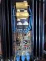
On my boat I have a 24v to 12v converter and from the 12v out it goes into this circuit, left connector, and the from the right connector i used to get 12v (but an 10 ohm resistance has be burnt and some thing else, that something I don’t know what is)
I possible I need help with two things,
1: why is this circuit needed
2: anyone that can help me identify the burned components")
Thanks in advance.
Dennis
On my boat I have a 24v to 12v converter and from the 12v out it goes into this circuit, left connector, and the from the right connector i used to get 12v (but an 10 ohm resistance has be burnt and some thing else, that something I don’t know what is)
I possible I need help with two things,
1: why is this circuit needed
2: anyone that can help me identify the burned components
Thanks in advance.
Dennis
Attachments
-
 229 KB Views: 54


