What happens when currents cross paths through an EMF and Resistor?

Thread Starter

Neil Hayes

Joined May 23, 2015
14
Hey there everyone!

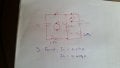
I just found this website there today and I can't wait to get stuck into the information contained in it. The question that I have relates to a question I'm trying to get an answer to. I haven't seen it happen before but after doing my KVL equations I find that an i1 current at .091A going in an anticlockwise direction passes through both a 12 v emf and 3 ohm resistor while an i2 current of .454A flows through the emf and resistor in a clockwise direction. I need to find the current flow through the battery and also the power dissipated in the 3 ohm resistor which I believe to be the .454A - the .091A and then that will enable me to find the voltage drop which in turn will give me the IxV for my power calculations.

Basically I've not seen this happen and it is counter intuitive to what I've learned already. I'm currently doing an electronic/electric engineering course and the info in the course is not 100% at times.

Any help or suggestions would be much appreciated.

Neil :)
 

MrChips

Joined Oct 2, 2009
30,824
You can't have two currents in the same element. Stick to labeling one current per element.

A circuit diagram would help greatly.
 

studiot

Joined Nov 9, 2007
4,998
Sounds to me like you have come across some form of mesh current analysis.

One form is known as Maxwell's method and works more or less exactly as you describe.

Edit you posted a circuit and it is exactly Maxwell's method.

The thing to remember is that in your diagram both I1 and I2 are notional or fictious currents that may or may not represent the actual currents in any given component.

They will coincide with the actual component current if the component is in a part of the loop that is not shared with another loop.

Component currents in shared parts will be the algebraic sum of both currents.
 

Thread Starter

Neil Hayes

Joined May 23, 2015
14
From my circuit analysis I found that the i1 current was -.091A when I assumed a clockwise direction so I've changed it to the anticlockwise as shown in the diagram. On this sites info about mess analysis it shows the same situation as the problem that I have but it doesn't have the emf in the branch concerned.
 

studiot

Joined Nov 9, 2007
4,998
Be careful, I did say there is more than one mesh current method.

Most American sources use the actual currents, not the assigned currents, so decide which you are going to chose.

This all works out the same because the equations are linear.

That is you derive a set of linear simultaneous equations between crurrents and voltages and suitable constants.

There are an infinite number of sets of suitable constants that satisfy the same set of solutions.
 

Thread Starter

Neil Hayes

Joined May 23, 2015
14
Be careful, I did say there is more than one mesh current method.

Most American sources use the actual currents, not the assigned currents, so decide which you are going to chose.

This all works out the same because the equations are linear.

That is you derive a set of linear simultaneous equations between crurrents and voltages and suitable constants.

There are an infinite number of sets of suitable constants that satisfy the same set of solutions.
The course I'm doing hasn't touched on mess currents at all. I've just learned how to use kvl loop methods for analysis. I'll try contacting the university again and see if I can get some better info maybe.
 

Jony130

Joined Feb 17, 2009
5,488
If we assume anticlockwise current I1 ans I2 we have:

For loop 1 we have

-12V + (I1 - I2)*3Ω + 13V+I1*1Ω = 0

For loop 2

-14V + (I2 - I1)*3Ω +12 + I2*2Ω = 0

And after we solve this

I1 = 1/11 A = 0.0909A
I2 = 5/11 A = 0.4545A

Since all current are positive, and this means that our assumptions about current direction was right.

3Ω resistor current is I1 - I2 = 0.0909A - 0.4545A = -0.3636A
And this "-" sign give us a info that 3Ω resistor current flow in opposite direction than I1 current.

Also notice I2 - I1 = 0.3636A So 3Ω resistor current flow in the same direction as I2 current.

http://forum.allaboutcircuits.com/attachments/14323999346811067057197-jpg.86225/
 

Thread Starter

Neil Hayes

Joined May 23, 2015
14
If we assume anticlockwise current I1 ans I2 we have:

For loop 1 we have

-12V + (I1 - I2)*3Ω + 13V+I1*1Ω = 0

For loop 2

-14V + (I2 - I1)*3Ω +12 + I2*2Ω = 0

And after we solve this

I1 = 1/11 A = 0.0909A
I2 = 5/11 A = 0.4545A

Since all current are positive, and this means that our assumptions about current direction was right.

3Ω resistor current is I1 - I2 = 0.0909A - 0.4545A = -0.3636A
And this "-" sign give us a info that 3Ω resistor current flow in opposite direction than I1 current.

Also notice I2 - I1 = 0.3636A So 3Ω resistor current flow in the same direction as I2 current.

http://forum.allaboutcircuits.com/attachments/14323999346811067057197-jpg.86225/
Thanks for the info there and the help. Is that the same story so for the current that passes through the 12 v emf?
 
Top