What happens after you switch off an inductor - after the spike that is!

Thread Starter

jamesinnewcastle

Joined Nov 5, 2009
14
Hi All
I was an electronics engineer for 45 years and have now retired. I never really designed things from first principles so I have decided to get down to design really basic circuits and cultivate a deep understanding. My first crack at this leaves me stuck at pretty much the first attempt. I hope that this is the right forum for this question!

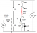
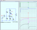
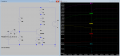
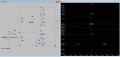
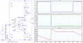
I decided to drive an inductance to see how it reacted. My simple circuit is attached (hopefully). I also attach the various waveforms I obtained. The 47R is intended to be a 'current sense', by monitoring the voltage across it I am assuming that I am measuring the current through it and so that through the inductance.

I have several questions about this but my first and basic one is: When the transistor is switched off, why does there appear to be current flowing? I assume this because of the voltage I see changing across the sense resistor. There are other questions about what is happening when the transistor is off, but this is the most basic.

I've read through various descriptions of this fairly basic coil-and-switch circuit, but while the large voltage spike is explained rather excitedly, there is no discussion of what happens after that or indeed after the spike reaches its peak. Also these texts tend to talk about the 'current' in the coil/circuit ignoring the open switch. Clearly there is some energy in the coil that must dissipate and I assume that the coil resistance does this, but what is causing the voltage across the sense resistor?

Cheers
James
 

Attachments

ericgibbs

Joined Jan 29, 2010
21,437
hi James,
Consider the magnetic field that is created around an Inductor due to the current flowing through the Inductor,
Switching Off the current flowing in the Inductor causes the magnetic field to collapse, which creates a high voltage across the Inductor.
Refer to Lenz's Law for the Induced voltage value, the faster the current turn Off the higher the voltage.
E
https://www.google.com/search?client=firefox-b-d&q=Lenzs+law
 

Papabravo

Joined Feb 24, 2006
22,081
The short answer is that after the energy from the magnetic field has dissipated the circuit returns to an equilibrium condition that depends entirely on the other components. That means that because Q1 represents an "open circuit", there is no current in R3 and the voltage across the inductor is identically zero. That's a pretty mundane result if you ask me.
 

WBahn

Joined Mar 31, 2012
32,794
Hi All
I was an electronics engineer for 45 years and have now retired. I never really designed things from first principles so I have decided to get down to design really basic circuits and cultivate a deep understanding. My first crack at this leaves me stuck at pretty much the first attempt. I hope that this is the right forum for this question!

I decided to drive an inductance to see how it reacted. My simple circuit is attached (hopefully). I also attach the various waveforms I obtained. The 47R is intended to be a 'current sense', by monitoring the voltage across it I am assuming that I am measuring the current through it and so that through the inductance.

I have several questions about this but my first and basic one is: When the transistor is switched off, why does there appear to be current flowing? I assume this because of the voltage I see changing across the sense resistor. There are other questions about what is happening when the transistor is off, but this is the most basic.

I've read through various descriptions of this fairly basic coil-and-switch circuit, but while the large voltage spike is explained rather excitedly, there is no discussion of what happens after that or indeed after the spike reaches its peak. Also these texts tend to talk about the 'current' in the coil/circuit ignoring the open switch. Clearly there is some energy in the coil that must dissipate and I assume that the coil resistance does this, but what is causing the voltage across the sense resistor?

Cheers
James
As you say, there is energy in the coil and it has to go somewhere.

Because the energy in an inductor is a function of current, and because energy has to be continuous, so must the current.

The voltage across an inductor is proportional to the rate at which the current is changing. As the transistor attempts to cutoff quickly, the coil current attempts to drop quickly, resulting in a very large voltage across it -- that voltage forces current to continue flowing in the transistor be causing a breakdown of the collector-base junction -- and event which is almost guaranteed to damage, if not destroy, the transistor. It may work for a while, but it likely will fail much sooner than expected.

The voltage across the sense resistor is a consequence of the current continuing to flow in the coil (since the two are in series), not the other way around.

To protect the transistor, you should put a diode in parallel with the coil such that it is reverse biased with the coil is energized. When the switch closes, the voltage at the bottom of the coil will only increase to one diode drop above the voltage at the top of the coil, at which point the diode will start conducting and provide a path for the coil current to circulate in the coil and the energy to dissipate as heat in both the diode and the coil. To get the energy to dissipate more quickly, you can put a resistor in series with the diode. The larger the resistor, the faster the decay -- but also the higher the voltage that will be produced, which will be seen by the collector of the transistor, so you need to take the breakdown voltage of the transistor into account.
 

Thread Starter

jamesinnewcastle

Joined Nov 5, 2009
14
Hi All

Thanks very much for your replies, and Eric I really appreciate the effort you put in with the Spice simulation, I'll study that more later.

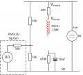
However I am still stuck on why there is current flowing in the sense resistor during the off period - have a look at the circuit attached. This is how I imagine the components to look with the transistor turned off, there is still energy in the coil, but how can any current flow in the resistor? There is no path for it to do so!

I can appreciate that the coil can be represented as having a resistor in parallel and so that can dissipate the energy in the coil, but there is no complete path for the current in the resistor so really the current in it should be zero (as soon as the transistor is fully off).

Any ideas on where the current is going?

Cheers
James
 

Attachments

WBahn

Joined Mar 31, 2012
32,794
There is only energy in the coil IF there is current flowing in the coil. The energy is proportional to the square of the current. No current, no energy. But the reverse is also true -- energy not zero means current not zero.

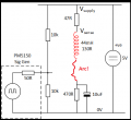
In your diagram, when the transistor switches off while there is current flowing in the coil, what you would have is an arc across the transistor in order to keep that current flowing. This is precisely how the ignition system in a car works. Get some current flowing in an inductor and then try to interrupt the current quickly. A voltage builds up to whatever is needed to keep the current flowing and, at some point, builds up high enough to cause an arc. The system is designed so that that arc occurs across the gap in the spark plug.

1688155208143.png

Look at the simulation result:

1688155308327.png
The voltage across the transistor spikes to about 6000 V. That transistor is going to break down and conduct current, even though it is ideally "off", well before it reaches that point.
 

WBahn

Joined Mar 31, 2012
32,794
I can appreciate that the coil can be represented as having a resistor in parallel and so that can dissipate the energy in the coil, but there is no complete path for the current in the resistor so really the current in it should be zero (as soon as the transistor is fully off).
It can be represented as having a resistor IN SERIES with it.

In order to prevent breakdown and/or arcing where you don't want it, you need to provide a parallel path for the current to decay through. That is what the diode that I described is for.
 

Irving

Joined Jan 30, 2016
5,107
Here's the LTSPICE simulation showing the collector/base/emitter currents - you can see the voltage spike initially causes breakdown of the collector-base junction and a high base current leading to an emitter current flowing through C1 - the supposedly OFF transistor is forced back ON, but not in a good way... long term this is destructive...

1688157615173.png

Putting a diode across L1 allows the demagnetising current in L1 to flow through D1 rather than the transistor and now we see the reverse current through L1 behaving as expected with the L/R time constant.

1688158242371.png
 
Last edited:

MrAl

Joined Jun 17, 2014
13,702
Hi All

Thanks very much for your replies, and Eric I really appreciate the effort you put in with the Spice simulation, I'll study that more later.

However I am still stuck on why there is current flowing in the sense resistor during the off period - have a look at the circuit attached. This is how I imagine the components to look with the transistor turned off, there is still energy in the coil, but how can any current flow in the resistor? There is no path for it to do so!

I can appreciate that the coil can be represented as having a resistor in parallel and so that can dissipate the energy in the coil, but there is no complete path for the current in the resistor so really the current in it should be zero (as soon as the transistor is fully off).

Any ideas on where the current is going?

Cheers
James
Hi,

The circuit you have there is very similar to a boost converter. That's a circuit that boosts a lower voltage up to a higher voltage. It does that by using an inductor. It works because the inductor generates a current of its own after the switch turns off, or at least tries to turn off. The inductor will do anything it can to keep that current flowing even after the switch is off. To achieve that, the voltage goes up to a higher and higher level in order to keep the current flowing through what ends up being a higher and higher resistance.

When the transistor is on, the current might be 100ma flowing down through the inductor. When the transistor TRIES to turn off, the inductor keeps the current of 100ma flowing for a short time. It eventually goes lower and lower according to the exponential rule for an RL circuit, R possibly being a variable here.

What this means is that the collector voltage will rise to a very high level and most likely blow out the transistor because the transistor would probably have a voltage rating much lower than the inductor voltage being produced.

Are you simulating this? If you try it with a real circuit the transistor may blow out suddenly without warning.

There are ways to prevent that from happening. In a boost converter the current is directed to the output. In a switching converter you may find a snubber circuit to help prevent the voltage from going too high. In a relay circuit that does not have to switch too fast, you may find a reverse connected diode.

If you would like to know more about this you should probably study a boost converter at least at the basic level.
 

WBahn

Joined Mar 31, 2012
32,794
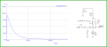
As you can see, using the diode protects the transistor from the inductive kickback spike, but it results in a slow decay of the inductor current over a period of about half a millisecond. This is because the discharging voltage is set by the forward drop of the Schottky diode, which is going to be somewhere in the 0.25 V range. This means that the decay rate of the inductor current is going to be roughly 6 mA/ms, assuming negligible inductor resistance. This is in the very rough ballpark of the simulation results. This may well be good enough for whatever purpose the coil is being used for, but if it isn't, putting a resistor in series with it can significantly decrease discharge time. If a 1 kΩ resistor is put in series with it, the initial voltage drop across that resistor will be about 15 V, which is no threat to the transistor, but which results in an initial discharge rate of about 350 mA/ms.

One thing to keep in mind is that simulations of events like this are problematic unless great care is taken to use models specifically designed to reasonably model those events and simulation parameters are likewise carefully chosen.

In this case, notice that the simulation results for the circuit without the anti-kickback diode shows that the the inductor is not only not continuous, which the laws of physics demand, but that it instantly reverses direction. The same for the collector current. Results like that indicate that something is happening that is not being modeled/simulated properly, but can't be relied upon for much more than that.
 

crutschow

Joined Mar 14, 2008
38,484
Note that an inductor carrying current, will do whatever it takes to keep the current flowing until the inductive energy is dissipated.

If the current is suddenly interrupted by a switch opening, the current will keep flowing and the voltage will rise until either the voltage flashes across the switch or breaks down the coil insulation, or the voltage gets high enough that all the energy goes into any capacitance across the inductor.
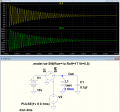
The circuit then forms a oscillating parallel LC circuit with the oscillations continue until all the energy in the coil has been dissipated;

Below is an example sim of a simple parallel LC circuit with a 1mH inductor with a 2 ohm series resistance in parallel with a 0.1µF capacitor, and nothing to limit (clamp) the spike..
The initial current is 5A, from the 10V supply, when the switch is opened.
The inductive spike then peaks to near 500V as the inductive energy transferred to the capacitor (minus the loss in the inductor resistance during that half cycle of oscillation).
The circuit then continues to oscillate, transferring remaining the energy back and forth between the inductance and capacitance with a near 90° phase-shift between the current and voltage, until all the energy is dissipated in the 2 ohm inductor resistor.

1688166154761.png
 
Last edited:

Thread Starter

jamesinnewcastle

Joined Nov 5, 2009
14
Hi All

Many thanks for the replies and the spice model from Irving will be a great help. Clearly there had to be some way for the current to flow and the base-collector junction being forward biassed is hopefully my answer. I think that I may have dismissed that because I would have thought that the base voltage would have been disturbed by that flow. I had chosen high value bias resistors just so that sort of effect would occur but I had forgotten that the signal generator has a low output impedance and may be absorbing any disturbance - I'll have to get closer with the scope to check that out. Some more hours of puzzling now!

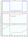
Forums are great but often responders don't read the question or go off topic in the excitement of sending a reply - I know because I do it all the time. So just to respond generally to comments you may think that I have ignored. I'm happy with the back EMF/voltage spike - I've suppressed many a relay with diodes over my career. I don't want to protect the transistor as it would change what I was trying to study, the transistor is still working and has been continuously for many hours. All the voltages I've shown are photos taken from my Tek7000 scope.

Interestingly the current in the inductor is linear compared with the Spice models. Getting a linear current was another of my (unspoken) things that I wanted to research.

Something I will need to look at later is why there is a sudden ringing in the last half of the 'OFF' time, and what is controlling the slope duration after the spike - that doesn't change with input pulse width.

Thanks to you all - I may be back with more pedantic questions!

Cheers
James
 

MrAl

Joined Jun 17, 2014
13,702
Hi All

Many thanks for the replies and the spice model from Irving will be a great help. Clearly there had to be some way for the current to flow and the base-collector junction being forward biassed is hopefully my answer. I think that I may have dismissed that because I would have thought that the base voltage would have been disturbed by that flow. I had chosen high value bias resistors just so that sort of effect would occur but I had forgotten that the signal generator has a low output impedance and may be absorbing any disturbance - I'll have to get closer with the scope to check that out. Some more hours of puzzling now!

Forums are great but often responders don't read the question or go off topic in the excitement of sending a reply - I know because I do it all the time. So just to respond generally to comments you may think that I have ignored. I'm happy with the back EMF/voltage spike - I've suppressed many a relay with diodes over my career. I don't want to protect the transistor as it would change what I was trying to study, the transistor is still working and has been continuously for many hours. All the voltages I've shown are photos taken from my Tek7000 scope.

Interestingly the current in the inductor is linear compared with the Spice models. Getting a linear current was another of my (unspoken) things that I wanted to research.

Something I will need to look at later is why there is a sudden ringing in the last half of the 'OFF' time, and what is controlling the slope duration after the spike - that doesn't change with input pulse width.

Thanks to you all - I may be back with more pedantic questions!

Cheers
James
Hello again,

It can't be that complicated. There is only one way for current to flow downward and that is through the transistor.
If the base collector is reverse biased (which it usually is except near saturation), then the leakage current plays a part in the conduction of the collector emitter current. The inductor raises the collector voltage, the leakage current increases, the transistor stays 'on' or turns back on in an unusual way. It stays on until the current decreases enough to let the transistor turn off fully. It would be an unusual process.

When converters are designed the mitigation of that high voltage collector spike is a major issue and has to be dealt with using appropriate circuitry to protect the transistor. Virtually every converter design takes this into consideration.

One piece of information may be missing here though, just how high does the collector voltage go when the spike appears, and what is the rating of the transistor. Is that a scope pic that shows the 170v peak and how does that compare to the transistor rating.
It appears that we may be seeing something that looks like resonance. The collector base capacitance and base emitter capacitance in conjunction with the coil. Since the spike shoots up, the collector base capacitance would provide more current to the base.

You also have to realize that transistors can get 'damaged' by high voltage spikes and still look like they are working. The damage accumulates until it fails.
 

MrAl

Joined Jun 17, 2014
13,702
Hello again,

Here is a workup of the basics of what is probably happening.
The transistor is replaced with a current controlled current source, and there is some collector base capacitance, and some inductor inefficiency added.
When the transistor turns on, the waveform shoots up and then comes back down.
The exact nature has to include nonlinearities of the transistor for which the transistor model shown here does not incorporate, as this is to show a more basic view of what is happening. We would also have to include a more comprehensive model of some of the other components too such as the change in capacitance with voltage. As a result of the approximations, we get a response that is similar in nature but not exact.
Note the inductor has some initial energy at t=0 and that is when the transistor turns off.

InductorSwitchingSpike-3.png
 

Thread Starter

jamesinnewcastle

Joined Nov 5, 2009
14
Hi All

Thanks again for all the responses, I suspect that this is going to be more a lesson for me about transistors rather than inductors!

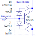
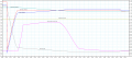
Danko - your model is the closest to the actual waveforms and reflects the 4 phases that I had originally spotted - and wondered about! I attach a comparison between them. Going through the phases then:

A: The transistor is turned off, we get the expected spike, however instead of the coil current falling to zero it goes negative (!). At this point (you can't see it at this scale) the collector is at -0.8V and, as the base is at 0.8V, the base-emitter junction is forward biassed! This must be the 'missing' current path.
B: In this period the inductor is again charging but with the opposite field direction (?) The decrease in current is linear and so the voltage across it must be constant.
C: This point looks to be that where the coil current falls to zero and is no longer building or falling. It looks as if the coil is no longer being driven and so a natural ringing response can happen.
D The transistor is turned on (by the C-E path that is). Now the coil current adopts the expected constant increase expected with a fixed applied voltage.

I still don't have a complete understanding of what is happening, Danko - it would be interesting to see the base current plotted on your model if you could please?

I think that this excercise proved to be more interesting that I had imagined!

Cheers
James
 

Attachments

Top