What exactly is the attached circuit is doing?

Thread Starter

haaad

Joined Jan 30, 2025
4
Hi All,

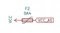
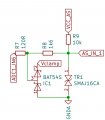
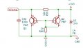
I have found this one in the net.

I am redesigning existing circuit for my needs and I would like to understand the source information.

What exactly attached circuit is doing? I cannot find anything similar with the theory behind it.

I would appreciate explanation, direction to existing sources, advice...

All the best from
HD
 

Attachments

Thread Starter

haaad

Joined Jan 30, 2025
4
When a current flows thru R59 the Q1 becomes conducting and clamps the Vclamp voltage by its EC structure.

It happens when Vclamp is higher than 3v3.
Thank you Michal,

Would you have any directions to theory behind it. I am really rusty in electronics (And I only got basics back in the past).
Or If you do not mind answering (simple for you) questions.

This was a bit out of context
Bit more context is attached:
I took it from https://openhomesecurity.blogspot.com/ and I do not want just to copy it I want to lear how it works (In general I do ;)

This is to work with burglar PIR sensors, so I guess all this is for signal conditioning.

Also what is this GND to AGND.

Best regards
HD
 

Attachments

ronsimpson

Joined Oct 7, 2019
4,646
The right transistor is just a diode. It makes a voltage that is about 0.65V less than the +3.3V supply.
The left transistor will turn on any time it's Emitter gets above 3.3V. It will be off if the Emitter is below 3.3V.
"Vclamp" is allowed to be up to about 3.3V. Above that the transistor shunts current to GNDA. (analog ground)
1738250544980.png
With out seeing the entire circuit I can only guess that the relationship is between the Analog and Digital Grounds is.
 

Thread Starter

haaad

Joined Jan 30, 2025
4
The right transistor is just a diode. It makes a voltage that is about 0.65V less than the +3.3V supply.
The left transistor will turn on any time it's Emitter gets above 3.3V. It will be off if the Emitter is below 3.3V.
"Vclamp" is allowed to be up to about 3.3V. Above that the transistor shunts current to GNDA. (analog ground)
View attachment 341538
With out seeing the entire circuit I can only guess that the relationship is between the Analog and Digital Grounds is.
Thanks Ron,

If you want - have a look into the link I have posted before. It is really nice blog on designing burglar alarm. Snapshots are from version 2.0.4

With your explanation I do get it.
I need learn more on circuit analysis.

I have stumbled on L4 calculation/selection - this is not explained during design nor in BOM. I do not want just to slap 0ohm R there. I would like to understand selection process of such inductor.

I like this guy (Robert Feranec) chanel - in this case ferrite beads. I am using his content to learn more...

There is loads to learn - So I took live example that I need and started asking questions.
You may ask why not just buy alarm... I did - Risco lightsys - but they want me to pay subscription for online connectivity now...
On the other hand I did not want simplistic solution like here https://projecthub.arduino.cc/rajun10/arduino-security-alarm-system-f38f99 - there is tons of it in the net.
I would like to build alarm system with parametric line(example above), ethernet connectivity, (*)GSM (these are "just" modules as per reference design slapped on SPI) and raspberry pico (why? I think it is great controller. I mean cheap and powerful and I have like 20 of them (10 spare))

Best regards
HD
 

atferrari

Joined Jan 6, 2004
5,001
Thanks Ron,

If you want - have a look into the link I have posted before. It is really nice blog on designing burglar alarm. Snapshots are from version 2.0.4

With your explanation I do get it.
I need learn more on circuit analysis.

I have stumbled on L4 calculation/selection - this is not explained during design nor in BOM. I do not want just to slap 0ohm R there. I would like to understand selection process of such inductor.

I like this guy (Robert Feranec) chanel - in this case ferrite beads. I am using his content to learn more...

There is loads to learn - So I took live example that I need and started asking questions.
You may ask why not just buy alarm... I did - Risco lightsys - but they want me to pay subscription for online connectivity now... On the other hand I did not want simplistic solution like here https://projecthub.arduino.cc/rajun10/arduino-security-alarm-system-f38f99 - there is tons of it in the net.
I would like to build alarm system with parametric line(example above), ethernet connectivity, (*)GSM (these are "just" modules as per reference design slapped on SPI) and raspberry pico (why? I think it is great controller. I mean cheap and powerful and I have like 20 of them (10 spare))

Best regards
HD
Not sure if much in line with what you are interested but this EE doesn't waste your time and goes straight to the point. Here
 

Thread Starter

haaad

Joined Jan 30, 2025
4
Not sure if much in line with what you are interested but this EE doesn't waste your time and goes straight to the point. Here
Hi,

Thanks for this.
It is always good to refresh and expand.
circuit 3.JPG
If I understand this ok and correct me if I am wrong.
GND being on digital side AGND on analog/ADC side - so the inductor reduce HF signals from GND to AGND...???

This may be stupid question:
Why L4 is where it is - at the ground? Usually I have seen it at Vcc (I did not see many things electronic wise yet)
Another one is zener diode usually comes with resistor to limit current...

BR
HD
 
Top