Facebook
 Google
 GitHub
 Linkedin
Hi,
I’m refurbishing an old Maas Rowe cathedral chime system. It consists of 18 small chime bars that are struck by solenoids. The bars each have small pickup coils that feed a preamp. I’ve looked for a schematic but no luck.
There is a transformer that powers the solenoids and there is a mystery capacitor across the transformer output. The voltage measures 27.4 volts across the output.
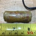
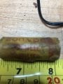
The problem is that it’s an old wax cap that I’m sure should be replaced and I’m not sure of the value. I’m think it reads 25uf 200VDC, but if could be .25uf as there is a scratch over the front part of the first digit. The two might be a three, but I’m pretty sure it’s a two. I’m sure it’s not 2.5uf. The cap is about 2.5” long and 5/8” diameter. It measures 2.0uf on my multimeter. There are a bunch of .1uf 200v caps in this unit that are about 2.5” long and .5” diameter and most measure anywhere from 550-1000uf with a couple as high as 1.5uf. There are three 15uf caps used in the amp power supply that all read about twice their listed rating.
One side of the power out goes to one side of all the solenoids which are only a foot or so away from the power supply. The other side of the power goes down a six foot cable to the keyboard used to switch on each note. These return through a multiwire cable and a jones plug back to the other sides of each corresponding solenoid. Each solenoid has a .1uf and large “domino” 400ohm resistor in parallel. I’ve seen snubbers that have a series resistor and cap in parallel with solenoids, but these solenoids are wired with the cap and resistor both in parallel.
So, my questions are, what is the purpose of the mystery capacitor by the transformer output, and what is the most likely value - .25uf or 25uf?
Thanks!
I’m refurbishing an old Maas Rowe cathedral chime system. It consists of 18 small chime bars that are struck by solenoids. The bars each have small pickup coils that feed a preamp. I’ve looked for a schematic but no luck.
There is a transformer that powers the solenoids and there is a mystery capacitor across the transformer output. The voltage measures 27.4 volts across the output.
The problem is that it’s an old wax cap that I’m sure should be replaced and I’m not sure of the value. I’m think it reads 25uf 200VDC, but if could be .25uf as there is a scratch over the front part of the first digit. The two might be a three, but I’m pretty sure it’s a two. I’m sure it’s not 2.5uf. The cap is about 2.5” long and 5/8” diameter. It measures 2.0uf on my multimeter. There are a bunch of .1uf 200v caps in this unit that are about 2.5” long and .5” diameter and most measure anywhere from 550-1000uf with a couple as high as 1.5uf. There are three 15uf caps used in the amp power supply that all read about twice their listed rating.
One side of the power out goes to one side of all the solenoids which are only a foot or so away from the power supply. The other side of the power goes down a six foot cable to the keyboard used to switch on each note. These return through a multiwire cable and a jones plug back to the other sides of each corresponding solenoid. Each solenoid has a .1uf and large “domino” 400ohm resistor in parallel. I’ve seen snubbers that have a series resistor and cap in parallel with solenoids, but these solenoids are wired with the cap and resistor both in parallel.
So, my questions are, what is the purpose of the mystery capacitor by the transformer output, and what is the most likely value - .25uf or 25uf?
Thanks!