What do these ports on a D flip-flop mean?

Thread Starter

pinkoryx

Joined Dec 11, 2017
47
Hello everyone,

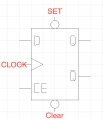
I am using CEDAR Logic Simulator and added this D flip-flop (Clock enabled, low active set/reset) to my work space, but the thing is I don't know what these 'ports' mean and what they are used for.

I have used the 'help' section on the program I'm using and google searched for info as well but found nothing.


Any help is greatly appreciated, thank you.
 

Attachments

MrChips

Joined Oct 2, 2009
30,821
Standard connections to a D-type flip-flop are:

Inputs
D-input
CLOCK
SET (or PRESET)
CLEAR (or RESET)

Outputs
Q
/Q

Power
Vcc (or VDD)
GND (or Vss)

A D-type flip-flop does not usually have a CE input.
 

dl324

Joined Mar 30, 2015
16,935
I have used the 'help' section on the program I'm using and google searched for info as well but found nothing.
That's one of my gripes about that simulator.

The top input is set bar, the bottom input is reset bar, CE is Clock Enable.

I determined this experimentally as, as you mentioned, there's no documentation.
 

WBahn

Joined Mar 31, 2012
30,071
Almost.
Standard practice is to put a bar over a label that is ACTIVE-LOW.

Hence put a bar over SET and CLEAR.
The preferred approach is to EITHER use a bubble on the pin and then the SET and CLEAR label OR to use the bar over the labels but have NO bubble. If you have both, then you actually have a double negative.

But that is for labels placed on the part, which is where they usually belong. The labels here are on the outside of the pins and are therefore describing the signals before they get to the bubble. That is asking for confusion no matter what you do.
 

MrChips

Joined Oct 2, 2009
30,821
The preferred approach is to EITHER use a bubble on the pin and then the SET and CLEAR label OR to use the bar over the labels but have NO bubble. If you have both, then you actually have a double negative.

But that is for labels placed on the part, which is where they usually belong. The labels here are on the outside of the pins and are therefore describing the signals before they get to the bubble. That is asking for confusion no matter what you do.
That is not how I was taught this.

The bar over the name is part of the name, such as making the label a different font, color, etc. Because of lack of type setting options, some use CLEAR* or CLEAR(L).

The bubble is added to the schematic drawing to represent the same thing. It is simply an indicator (or reminder) that the signal is ACTIVE-LOW. The two together serve the same purpose. They do not cancel each other.
 

WBahn

Joined Mar 31, 2012
30,071
That is not how I was taught this.

The bar over the name is part of the name, such as making the label a different font, color, etc. Because of lack of type setting options, some use CLEAR* or CLEAR(L).

The bubble is added to the schematic drawing to represent the same thing. It is simply an indicator (or reminder) that the signal is ACTIVE-LOW. The two together serve the same purpose. They do not cancel each other.
There are definitely two camps on this, but I believe the dominant one now -- and the one embodied by the ANSI symbol standard, is that labels inside the block represent internal logic states. So an R on the block means reset if, internally, it is HI. An inversion bubble on the block input pin means that the state of the internal signal is opposite that of the external signal.
 
Top