Facebook
 Google
 GitHub
 Linkedin

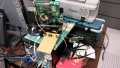
Now it's time to build the power signal generator test unit with a 8-bit controller.
The PIC18F14Q41 will the controller used because it has some nice analog functions.
https://www.microchip.com/en-us/pro...erals/integrated-analog/operational-amplifier
https://www.microchip.com/en-us/pro...dent-and-analog-peripherals/integrated-analog
8-bit DAC for sine wave generation
Digitally controlled OP amp for signal buffering and level control.
Using a simple 8-bit uint8_t sine table with a indexing loop we generate the analog signal in a timing loop of ASM nop instructions and volatile variables to stop optimization.
We don't need the full 8-bits to create a usable signal and it needs to be at least 9 kHz so we index by 4 for analog data steps.
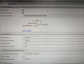
Using MCC, we do a quick setup of DAC2
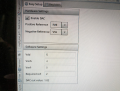
Config our DAC ref voltage for the analog level we need.
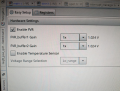
Config the OPA for the analog signal buffer output gains input/outputs we need. We can program the gain resistor ladder using a GPIO interrupt so we don't need to poll during our frequency timing loop.
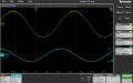
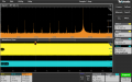
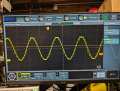
The result is a usable signal (we can stop, start and adjust in amplitude) to feed a audio amplifier for the resonant magnetic wireless coupling loop.
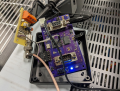
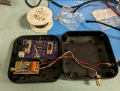
What's left is to make a power, signal and HID interface prototype board and to tidy up a simple button/led user interface for a project box.
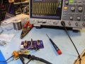
Then design a custom PCB instead of using one of my old designs made for serial protocol conversion.
The PIC18F14Q41 will the controller used because it has some nice analog functions.
https://www.microchip.com/en-us/pro...erals/integrated-analog/operational-amplifier
https://www.microchip.com/en-us/pro...dent-and-analog-peripherals/integrated-analog
8-bit DAC for sine wave generation
Digitally controlled OP amp for signal buffering and level control.
Using a simple 8-bit uint8_t sine table with a indexing loop we generate the analog signal in a timing loop of ASM nop instructions and volatile variables to stop optimization.
C:
    while (true) {
        Nop();
        Nop();
        Nop();
        Nop();
        Nop();
        Nop();
        DAC2_SetOutput(sine_wave[sine_index = sine_index + (uint8_t)sine_skip]);
    }

// sine.h
#define sine_skip    4

const uint8_t sine_wave[256] = {
  0x80, 0x83, 0x86, 0x89, 0x8C, 0x90, 0x93, 0x96,
  0x99, 0x9C, 0x9F, 0xA2, 0xA5, 0xA8, 0xAB, 0xAE,
  0xB1, 0xB3, 0xB6, 0xB9, 0xBC, 0xBF, 0xC1, 0xC4,
  0xC7, 0xC9, 0xCC, 0xCE, 0xD1, 0xD3, 0xD5, 0xD8,
  0xDA, 0xDC, 0xDE, 0xE0, 0xE2, 0xE4, 0xE6, 0xE8,
  0xEA, 0xEB, 0xED, 0xEF, 0xF0, 0xF1, 0xF3, 0xF4,
  0xF5, 0xF6, 0xF8, 0xF9, 0xFA, 0xFA, 0xFB, 0xFC,
  0xFD, 0xFD, 0xFE, 0xFE, 0xFE, 0xFF, 0xFF, 0xFF,
  0xFF, 0xFF, 0xFF, 0xFF, 0xFE, 0xFE, 0xFE, 0xFD,
  0xFD, 0xFC, 0xFB, 0xFA, 0xFA, 0xF9, 0xF8, 0xF6,
  0xF5, 0xF4, 0xF3, 0xF1, 0xF0, 0xEF, 0xED, 0xEB,
  0xEA, 0xE8, 0xE6, 0xE4, 0xE2, 0xE0, 0xDE, 0xDC,
  0xDA, 0xD8, 0xD5, 0xD3, 0xD1, 0xCE, 0xCC, 0xC9,
  0xC7, 0xC4, 0xC1, 0xBF, 0xBC, 0xB9, 0xB6, 0xB3,
  0xB1, 0xAE, 0xAB, 0xA8, 0xA5, 0xA2, 0x9F, 0x9C,
  0x99, 0x96, 0x93, 0x90, 0x8C, 0x89, 0x86, 0x83,
  0x80, 0x7D, 0x7A, 0x77, 0x74, 0x70, 0x6D, 0x6A,
  0x67, 0x64, 0x61, 0x5E, 0x5B, 0x58, 0x55, 0x52,
  0x4F, 0x4D, 0x4A, 0x47, 0x44, 0x41, 0x3F, 0x3C,
  0x39, 0x37, 0x34, 0x32, 0x2F, 0x2D, 0x2B, 0x28,
  0x26, 0x24, 0x22, 0x20, 0x1E, 0x1C, 0x1A, 0x18,
  0x16, 0x15, 0x13, 0x11, 0x10, 0x0F, 0x0D, 0x0C,
  0x0B, 0x0A, 0x08, 0x07, 0x06, 0x06, 0x05, 0x04,
  0x03, 0x03, 0x02, 0x02, 0x02, 0x01, 0x01, 0x01,
  0x01, 0x01, 0x01, 0x01, 0x02, 0x02, 0x02, 0x03,
  0x03, 0x04, 0x05, 0x06, 0x06, 0x07, 0x08, 0x0A,
  0x0B, 0x0C, 0x0D, 0x0F, 0x10, 0x11, 0x13, 0x15,
  0x16, 0x18, 0x1A, 0x1C, 0x1E, 0x20, 0x22, 0x24,
  0x26, 0x28, 0x2B, 0x2D, 0x2F, 0x32, 0x34, 0x37,
  0x39, 0x3C, 0x3F, 0x41, 0x44, 0x47, 0x4A, 0x4D,
  0x4F, 0x52, 0x55, 0x58, 0x5B, 0x5E, 0x61, 0x64,
  0x67, 0x6A, 0x6D, 0x70, 0x74, 0x77, 0x7A, 0x7D
};Using MCC, we do a quick setup of DAC2
Config our DAC ref voltage for the analog level we need.
Config the OPA for the analog signal buffer output gains input/outputs we need. We can program the gain resistor ladder using a GPIO interrupt so we don't need to poll during our frequency timing loop.
The result is a usable signal (we can stop, start and adjust in amplitude) to feed a audio amplifier for the resonant magnetic wireless coupling loop.
What's left is to make a power, signal and HID interface prototype board and to tidy up a simple button/led user interface for a project box.
Then design a custom PCB instead of using one of my old designs made for serial protocol conversion.