What are these strange chips?

Thread Starter

pleriche

Joined Oct 29, 2017
84
I've been tearing downfaile LED lamps and the latest is the most interesting but the most puzzling. This is a dimmable 6W BC with impressive heatsinking, branded Lemnis Lighting. The highly sophisticated controller contains 2 bridge rectifiers on the AC input, 2 ferrite transformers a TI UCC28600 controller, a 358 dual opamp, an optocoupler, a power MOSFET and several discrete SM transistors and passives. No crumby capacitor-based current limiter here!

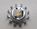
But strangest of all is the luminous head, shown in the first photo. Instead of the usual array of 5050 (or smilar) LED packages we have just 4 COB LEDs, plus 2 other copper-coloured COB devices with just 2 wire bonds each and a transparent covering. There are just 2 connections from the luminous head to the controller.

I'm completely stumped as to what the copper-coloured chips could be. They don't look at all like LED chips. If they were for thermal or luminoous monitoring they'd need their own connections to the controller. Any ideas?
 

Attachments

dl324

Joined Mar 30, 2015
16,846
I'm completely stumped as to what the copper-coloured chips could be. They don't look at all like LED chips. If they were for thermal or luminoous monitoring they'd need their own connections to the controller.
All LEDs will have one or more bond wires on the top of the die because that's the anode connection. The cathode connection is usually the backside of the LED die.
Any ideas?
My guess would be that they're LEDs used to affect the bulbs color temperature (.e.g. red to make the light color warmer).

How are they connected? Since you're working on defective bulbs, you could connect one to a constant current source of an appropriate value to see if they light. Not lighting wouldn't be definitive because the LED could be defective.
 

Thread Starter

pleriche

Joined Oct 29, 2017
84
Thank you Dennis for taking the trouble to reply. I scraped off the top protective layer to expose the copper tracks:
Img_4273a.jpg
All 6 devices are evidently in series. The 2 LEDs of the left light up nicely with a clear white light with 5V through 330Ω. Both in series light up dimly with the same. But this is with -ve on the thin track which would appear to be the bond wire connection and hence the cathode. (You would have thought the die would be bonded to the larger area of copper.)

Neither of the LEDs on the right light up. The top right one has been damaged by my scraping and possibly in both the die or bond wire have become detatched from the copper.

The 2 copper coloured chips don't light up, even with 9V though 8.2k. My DVM sees them as o/c even on the 20MΩ range. They don't look at all like LEDs. Some sort of PTC device for temperature compensation wouldn't make much sense as the control circuit appears to be a current source, and why wouldnt they just have a blob of black epoxy like most COB devices? I'm out of ideas.

I think in fact this may have been the first LED lamp I ever bought some 10 years ago, when they first came out. By the standards of today's bargain basement Far Eastern imports, it's incredibly over-engineered.
 

Thread Starter

pleriche

Joined Oct 29, 2017
84
Those look a lot like photocells.
You mean photovoltaic cells? I see the possible resemblence, but what on earth would they be doing in series with 4 LEDs driven from a current source? They both test o/c on my DVM, both on the 20MΩ and diode test ranges, either polarity. Some kind of protection device? But strange they both failed.
 

dl324

Joined Mar 30, 2015
16,846
You mean photovoltaic cells? I see the possible resemblence, but what on earth would they be doing in series with 4 LEDs driven from a current source?
It's unlikely that they're photocells being used to control brightness. Not with them being in series with the LEDs which were likely to be drawing significant current.
 

dl324

Joined Mar 30, 2015
16,846
Interesting thought, but everybody else just exposes a gold plated pad as a test point.
To solve this mystery, you're going to need a part that still works or information from the manufacturer. I'm still going with they're LEDs used to change the warmness of the emitted light.

If you could determine where the bond wires are connected, it would be helpful. Removing the encapsulation and trying to probe them will likely not work. Bond wires are very fragile.
 

Thread Starter

pleriche

Joined Oct 29, 2017
84
Pretty sure it doesn't. It'd need more than 2 connections to the electronics if it did. I've checked there are no paths to the heatsink and hence no return path through it.
 

Thread Starter

pleriche

Joined Oct 29, 2017
84
I have the answer! They are in fact red LEDs, presumably for colour correction.

I lifted one of them off the substrate. It came off with its transparent covering, which I cut away to get access to the bond wires. With my DVM on the diode range, I made contact with the back of the chip with one pin and the bond wires with the other. The bond wires were definitely the cathode. But with it upside down I couldn't see the face, and hence whether it was one or two LED chips.

So I tried very carefully removing the transparent covering from the other chip, still bonded to the substrate. (The covering is very soft silicone or similar.) Hence I got access to the bare die, still with a fragment or two of bond wire. Touching the positive pin to the base of the die or the land it was bonded to (or meant to be), it seemed to light up if I touched the negative pin on the top surface of the die. Tat is, it did for a while, because I think I must have damaged the die with my pins.

So I went back to the first die, and thought for a while how I could bond it to a conducting surface so I could contact its base whilst probing the bond wires, with the face of the die visible. I eventually hit on the idea of putting a blob of solder on a piece of copper foil then pressing the die into it while molten. On the second attempt this worked. The whole die lit up bright orange. I tried to take a photo but it was hopelessly overexposed. I might try again tomorrow, limiting the current to microamps and will post the result if I get one.

So that just leaves with the question of how the engineers came up with such a design. If I wanted to adjust the colour temperature of a lamp, I would have thought "just throw in a couple of red LEDs in series" would have been a pretty rough and ready way of doing it. If you want to make a white source with red, green and blue LEDs you have to set the currents in them a lot more precisely.

This seems to be very much a 1st generation LED lamp from a Dutch manufaturer, before the Far East started turning out bargain basement versions with much simpler engineering. It would be fascinating to speak to the original designers.
 

Thread Starter

pleriche

Joined Oct 29, 2017
84
So here it is, glowing bright orange, though not very well in focus. Some 10's of k in series with the multimeter (on diode range) test leads so as not to overexpose the photo. It looks like the square patterns you can see in earlier photos is metalisation to spread the current acros the top surface of the die.
Img_4286a.jpg
 

dl324

Joined Mar 30, 2015
16,846
So that just leaves with the question of how the engineers came up with such a design. If I wanted to adjust the colour temperature of a lamp, I would have thought "just throw in a couple of red LEDs in series" would have been a pretty rough and ready way of doing it. If you want to make a white source with red, green and blue LEDs you have to set the currents in them a lot more precisely.
It depends on what the engineers have to work with.

If you're Cree and make LEDs and LED bulbs, you have the option of modifying the phosphor used in the LEDs to affect final color.

If you just buy ready made LEDs to put in your bulbs, you're limited by what is available and do whatever you need to do to change the color.

If you have high enough volume to justify the cost of having custom LEDs made, you could go that route.

Early white LEDs used red, green, and blue LEDs to make white. Later, they started using blue LEDs and phosphors to make white.
 
Top