 Facebook
 Google
 GitHub
 Linkedin
Hi
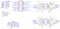
I'm designing a rudimentary circuit for measuring the cell voltages of an 8 cell LiFePO4 battery pack. Before anyone suggests using custom BMS chips like bq76930 et al, let me just say that I am already working on a BMS based around such a chip. This project is ONLY about measuring cell voltages with a small degree of accuracy, say to 2 decimal places. Cells voltage will typically be between 2 and 3.7V - this will be measured using the ADC on an Arduino or a MCU running 5V.
I have tried a few designs using MUXs to select and switch the cell - and + lines, but failed due to the total voltage across the pack exceeding the specifications of the MUX being used. I've now moved to a different approach (and one that others have tried, albeit with fewer cells being measured) using an op amp per cell. Essentially, the circuit consists of 8 op amps configured as voltage followers (the role of these is simply to limit current from each cell) and these provide the voltage from each cell, nominally 3.6, 7.2, 10.8...and so on up to cell 8 (28.4).
A further 8 op amps will then be configured as differential amps to get the voltage difference between C1 and GND, C2 and C1, C3 and C2... C8 and C7.
Each of these will use identical resistors to give Unity gain so the cell voltage can be read directly without any multipliers.
Finally, a 8:1 MUX will be used by the MCU to select which cell voltage to be measured...and each of these are expected to be well below 5V.
Now my question...
If the op amps are powered directly by the pack voltage (say between 23V and 28V) then what, if any, are the problems with this design? My reading of op amps states that they are in some ways limited by their voltage extremes - in my case this is likely to be 0V to 23-28V.
If I use an op amp which can operate with up to 36V and with a low Vos, what gotchas am I likely to run into?
I've attached a circuit diagram showing the main components.
Cheers
Mike
Attachments
-
 160.4 KB Views: 51
Last edited:

") This recently came up in another forum and as I recall even using the same operational amplifier.
This recently came up in another forum and as I recall even using the same operational amplifier.

